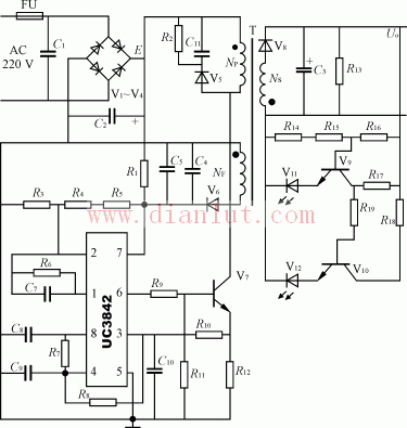
3842 charger circuit diagram
In Fig. 1, C1, V1~V4, C2 form a filter rectifier circuit, transformer T is a high frequency transformer, V5, R2, C11 constitute a protection circuit of power switch tube V7, and NF is a winding for supplying IC power. The single-ended output IC is UC3842, its 8 pin outputs 5V reference voltage, 2 pin is inverting input, 1 pin is amplifier output, 4 pin is oscillation capacitor C9, resistor R7 input terminal, 5 pin is grounding, 3 feet is The flow protection end, 6 feet for the single pulse output, and 7 pin for the power input. R6 and C7 form negative feedback. When the IC starts, the starting voltage is supplied by R1. After the circuit starts, the potential generated by NF is rectified and filtered by V6, C4 and C5 to supply the IC working voltage. R12 is an overcurrent protection sampling resistor, and V8 and C3 form a flyback rectification and filtering output circuit. R13 is the internal load, and V9~V12 and R14~R19 form the LED display circuit. In Figure 1, V5 and V6 select FR107, V8 selects FR154, and V7 selects K792.

Draw-wire sensors of the wire sensor series measure with high linearity across the entire measuring range and are used for distance and position measurements of 100mm up to 20,000mm. Draw-wire sensors from LANDER are ideal for integration and subsequent assembly in serial OEM applications, e.g., in medical devices, lifts, conveyors and automotive engineering.
Linear Encoder,Digital Linear Encoder,Draw Wire Sensor,1500Mm Linear Encoder
Jilin Lander Intelligent Technology Co., Ltd , https://www.jilinlandertech.com