Since the US Federal Communications Commission authorized the 3.1 to 10.6 GHz band in 2002, UWB filters have become a research hotspot in the UWB system. In recent years, domestic and foreign scholars have carried out a lot of research on UWB filters, and filters of various structures have also been proposed. For example, multimode resonators are widely used in the design of various types of ultra-wideband filters [1-3]. Document [1] proposes an improved multimode resonator that can generate two transmission zeros out of band to improve filter selectivity. In the literature [3], the folded multimode resonator is loaded at the center of the microstrip, so that the out-of-band characteristics of the filter are greatly improved. At the same time, since the transition structure of the coplanar waveguide (CPW) and the microstrip line can produce an ultra-wideband effect, it is often used in the design of bandpass filters [4-9]. However, usually the transition structure has no zero point in the lower stop band, so its selectivity is not good and the upper stop band is also narrow. Defective microstrip [10-11] and defective ground [12] structures are also commonly used to design ultra-wideband filters. However, the defect structure causes etching problems in the microstrip or ground plane, which causes signal integrity problems.
Based on the traditional CPW to microstrip transition structure, the microstrip at the center position is replaced by the interdigital coupling line to bring a transmission zero point in the upper and lower stopbands of the filter, thus improving the selectivity of the filter. Eight microstrip short-circuit stubs are loaded under the filter CPW slot to extend the upper stopband characteristics of the filter. Finally, in order to verify the filter performance, the processed filter was tested, and the test and simulation results were in good agreement.
1 UWB filter design
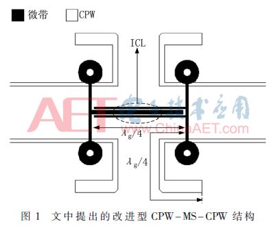
The filter proposed in this paper is designed on a Rogers RO 4350 (dielectric constant εr = 3.66) substrate with a thickness of 0.508 mm. The front copper foil constitutes the CPW, and the reverse copper foil acts as the strip line of the microstrip. This paper proposes an improved CPW to microstrip transition structure (CPW-MS-CPW), the basic structure of which is shown in Figure 1. The length of the coupling line and the CPW bending branch is about λg/4 of the center frequency. Unlike the traditional CPW to microstrip transition structure in [5], the central microstrip is replaced by an interdigital coupled line (ICL). Figure 2 shows the low-frequency lumped equivalent and J-transform equivalent circuit of the transition structure. Among them, the J transform network is realized by the transition of CPW and microstrip, and ICL can be equivalent to asymmetric parallel coupled line. C0 represents the low-frequency equivalent capacitance of the interdigital coupling line, and L0 and L1 represent the equivalent inductances of the intermediate conductor and the ground portion of the CPW, respectively.

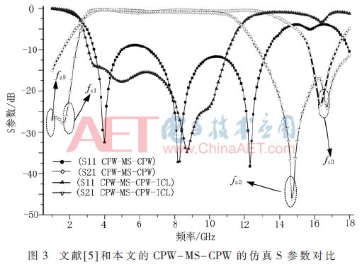
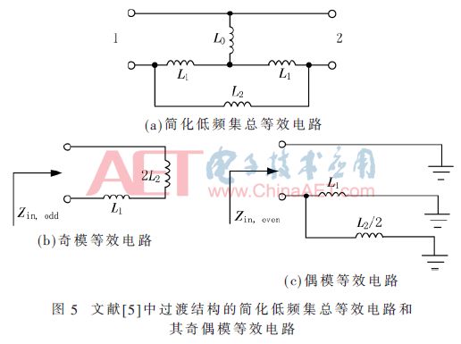
The simulated S-parameters of the improved and traditional hybrid CPW and microstrip structures are shown in Figure 3. The transition structure loaded with the interdigital coupling line has four transmission zeros out of the band. Among them, fz3 is generated by CPW to microstrip transition, and fz0 (0 GHz) and fz2 are introduced by ICL. For the transmission zero point fz1, the generation mechanism can be derived from its low-frequency equivalent lumped circuit analysis. The simplified circuits of the CPW-MS-CPW proposed in the paper and the low-frequency lumped equivalent circuit of the transition structure in [5] are shown in Fig. 4(a) and Fig. 5(a), respectively.
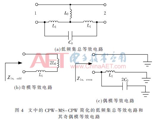
For the odd-mode excitation, it is obtained by its odd-mode equivalent circuit (as shown in Fig. 4(b)), and its input impedance is as shown in equation (1):

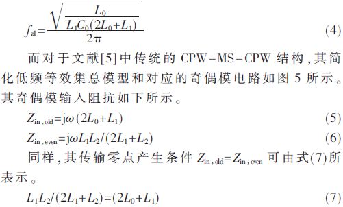
Obviously, consistent with the electromagnetic simulation results in Figure 3, this traditional transition structure does not produce any transmission zeros in the low frequency band except for 0 GHz.
From the above analysis, it is known that by introducing ICL, a transmission zero point is generated at the high end and the low end of the stop band, respectively. As shown in Fig. 3, the selectivity of the CPW-MS-CPW proposed in the paper is greatly improved compared to the transition structure in which no ICL is added in the literature [5]. However, the upper stopband characteristics of the filter are still not ideal, for example, the frequency at which the upper stopband attenuation reaches 20 dB does not exceed 15 GHz.
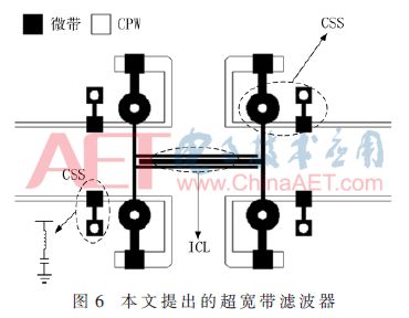
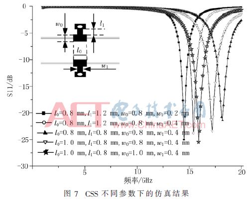
To further improve the out-of-band characteristics of the filter (as shown in Figure 6), four short-circuit stubs (CSS) are loaded by coupling in the CPW slot of the input and output ports of the filter to expand the upper stopband frequency. In addition, by introducing four short-circuit branches under the CPW bending groove, a transmission zero is generated at the upper pass band edge, thereby improving the selectivity of the filter in the high frequency band. As shown in Figure 6, the CSS proposed in this paper can be equivalent to a series LC resonator. Figure 7 shows the S21 simulated by CSS under different parameters. Obviously, CSS can generate transmission zeros in the high frequency band to improve the out-of-band characteristics of the filter with little effect on the passband. And its transmission zero point moves to the high frequency band as the parameters l0, w0, l1 decrease, but when the parameter w1 is decreased, the zero point moves to the low frequency band.
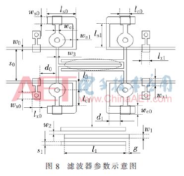
The filter parameters are shown in Figure 8. Filter size: w0=0.24 mm, s0=3.5 mm, lx0=0.8 mm, wx0=0.8 mm, d0=1.54 mm, ws0=0.8 mm, ls0=2.88 mm, wc1=0.43 Mm, ws1=0.36, w3=0.2 mm, l3=0.96 mm, lc1=1.78 mm, d1=1.04 mm, ls1=2.57 mm, lc0=0.95 mm, lx1=0.8 mm, wx1=0.8 mm, wc0=0.96 mm , w1 = 0.25 mm, w2 = 0.1 mm, g = 0.15 mm, l1 = 6.01 mm.
2 Filter analysis of results
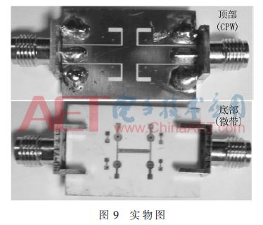
In order to verify the performance of the proposed filter, the filter designed in this paper is processed and tested. The physical object is shown in Figure 9. Figure 10 shows the filter S parameters and group delays measured with the vector. Obviously, the measured and simulated results have good consistency.
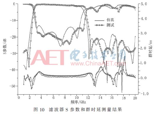
Test results show that the relative bandwidth of the filter is 123% (2.75 ~ 11.55 GHz). The return loss over the entire ultra-wideband is better than 15 dB. The insertion loss in most bands (3 to 10.2 GHz) in the passband does not exceed 0.7 dB, with a minimum insertion loss near the center frequency of less than 0.4 dB. Obviously, since the filter has a transmission zero at the upper and lower edges of the passband, which has a steep selectivity, the filter selection factor SF (3 dB bandwidth / 30 dB bandwidth) reaches 0.86. At the same time, the filter has a relatively flat group delay, and the group delay fluctuations in the entire ultra-wideband do not exceed 0.15 ns.
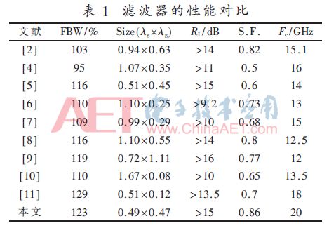
The performance pairs of the filters and other reported filters are shown in Table 1. Obviously, compared to some already published filters like CPW and microstrip hybrid structure [4-9], the proposed filter has a relatively compact size (0.49 λg × 0.47 λg, where λg represents a corresponding frequency of 6.85). GHz guided wave wavelength), wider bandwidth and steeper selectivity. Compared with the literature [5], since the interdigital coupling line is introduced in the paper, the selectivity of the filter is greatly improved, and the selectivity is the best in Table 1. In addition, by loading the coupling short-circuit branch under the corresponding slot of the CPW, the frequency Fc of the upper stop band suppressing more than 20 dB reaches 20 GHz, which is the highest frequency of the upper stop band in Table 1.
3 Summary
Based on the CPW-microstrip line-CPW transition structure, an ultra-wideband filter is designed. The interdigital coupling line is introduced at the center of the microstrip, resulting in a transmission zero at the lower edge of the passband, improving the selectivity of the filter (selection factor of 0.86). And loading the coupling short-circuit branch under the CPW slot further improves the selectivity of the filter and extends the upper stopband frequency of the filter. At the same time, the measured results show that the filter has the advantages of small insertion loss (0.7 dB), good return loss (greater than 15 dB) and good stop-band rejection, which makes the filter suitable for UWB wireless systems. .
16+ Years Experience Smart Watch manufacturer, ITOPNOO Provide One-stop Smart Wearable devices Solutions For You.
Our Smart Wearable products include android smart watches, Watch For iPhone, Bracelet and Wristband etc.
Leading healthcare navigation services for individuals and families who are generally healthy or face serious medical issues, and health services for employers.
The Trends New Watches Designs. Custom smart watch products designed with the vision of our clients' brands in mind.
Wholesale smart watches,Best Smart Watches,Gifts Wholesalers, smart watch manufacturer
TOPNOTCH INTERNATIONAL GROUP LIMITED , https://www.mic11.com