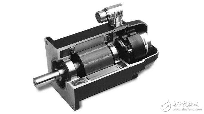
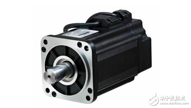
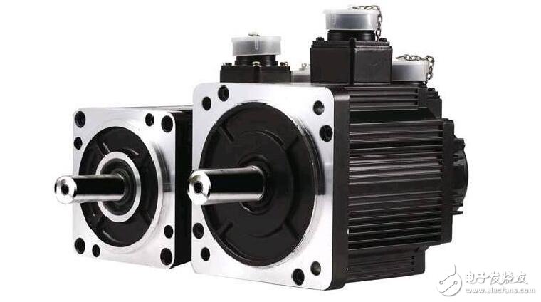
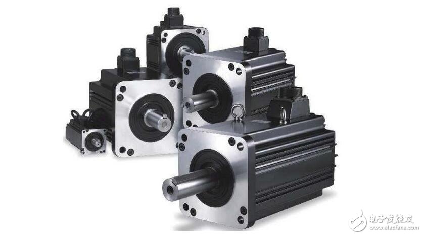
A servo motor is an engine that controls the operation of a mechanical component in a servo system, and is an auxiliary motor indirect transmission. The servo motor can control the speed and position accuracy very accurately, and can convert the voltage signal into torque and speed to drive the control object. The servo motor rotor speed is controlled by the input signal and can react quickly. It is used as an actuator in the automatic control system, and has the characteristics of small electromechanical time constant, high linearity, and starting voltage, which can receive the received electrical signal. Converted to an angular displacement or angular velocity output on the motor shaft. Divided into two major categories of DC and AC servo motor, its main feature is that when the signal voltage is zero, there is no rotation phenomenon, and the rotation speed decreases uniformly with the increase of torque.

1. The motor can't rotate after power-on, but there is no abnormal noise, no smell or smoke.
(1) Cause of failure
1 power is not connected (at least two phases are not connected);
2 fuse is blown (at least two phases are blown);
3 overcurrent relay is adjusted too small;
4 Control device wiring error.
(2) Troubleshooting
1 Check the power circuit switch, whether there is a breakpoint at the fuse and junction box, and repair;
2 Check the fuse type, the cause of the fuse, and replace the fuse;
3 adjust the relay setting value to match the motor;
4 Correct the wiring.
2. The motor does not turn after the power is turned on.
(1) Cause of failure
1 The rotor winding has an open circuit (one phase disconnection) or the power supply loses phase;
2 The winding end of the winding lead wire is connected incorrectly or the winding is internally reversed;
3 power circuit contacts are loose, contact resistance is large;
4 the motor load is too large or the rotor is stuck;
5 power supply voltage is too low;
6 small motor assembly is too tight or the grease inside the bearing is too hard;
7 bearings are stuck.
(2) Troubleshooting
1 identify the breakpoint to be repaired;
2 check the polarity of the winding; determine whether the winding end is correct;
3 Fasten the loose connecting screws and use a multimeter to judge whether the joints are falsely connected and repair them;
4loading or detecting and eliminating mechanical failure,
5 Check whether the specified surface connection method is misconnected; whether the voltage drop is too large due to the power supply wire is too large, and correct it;
6 new assembly makes it flexible; replace qualified grease;
7 repair bearings.
3. The motor is difficult to start. When the rated load is used, the motor speed is lower than the rated speed.
(1) Cause of failure
1 power supply voltage is too low;
2-sided connection motor misconnection;
3 rotor is welded or broken;
4 The rotor local coil is misconnected and reversed;
3 When the motor winding is repaired, the number of turns is increased too much;
5 Motor overload.
(2) Troubleshooting
1 measure the power supply voltage and try to improve it;
2 correct the connection;
3 check the welding and breakpoints and repair;
4 Check the misconnections and correct them;
5 restore the correct number of turns;
6 load shedding.
4. The motor no-load current is unbalanced, and the three-phase phase difference is large.
(1) Cause of failure
1 winding the first end of the winding is wrong;
2 power supply voltage imbalance;
3 windings have faults such as turn-to-turn short circuit and reverse coil connection.
(2) Troubleshooting
1 check and correct;
2 measure the power supply voltage and try to eliminate the imbalance;
3 Eliminate winding faults.

5. When the motor is running, the sound is abnormal and there is abnormal noise.
(1) Cause of failure
1 bearing wear or foreign matter such as sand in the oil;
2 the rotor core is loose;
3 bearings are short of oil;
4 The power supply voltage is too high or unbalanced.
(2) Troubleshooting
1 Replace the bearing or clean the bearing;
2 overhaul the rotor core;
3 refueling;
4 Check and adjust the power supply voltage.
6, the motor vibration is large during operation
(1) Cause of failure
1 due to excessive wear bearing clearance;
2 air gap is not uniform;
3 rotor imbalance;
4 shaft bending;
5 Coupling (pulley) coaxiality is too low.
(2) Troubleshooting
1 overhaul the bearing and replace if necessary;
2 adjust the air gap to make it uniform;
3 correct rotor dynamic balance;
4 straight shafts;
5 Recalibrate to make it compliant.
7, the bearing is overheated
(1) Cause of failure
1 too much or too little grease;
2 oil quality is not good with impurities;
3 The bearing is not properly matched with the journal or end cap (too loose or too tight);
4 bearing inner hole eccentric, rubbing with the shaft;
5 motor end cover or bearing cover is not flat;
6 The motor and load coupling is not corrected, or the belt is too tight;
7 bearing clearance is too large or too small;
8 The motor shaft is bent.
(2) Troubleshooting
1 add grease according to the regulations (1/3-2/3 of the volume);
2 replace the clean lubricating grease;
3 over-loose can be repaired with adhesive, over-tightening the car, grinding the journal or the inner hole of the end cap to make it suitable;
4 repair the bearing cover to eliminate the rubbing point;
5 re-assembly;
6 recalibrate and adjust the belt tension;
7 replace the new bearing;
8 Correct the motor shaft or replace the rotor.
8, the motor is overheated and even smoke
(1) Cause of failure
1 power supply voltage is too high;
2 The power supply voltage is too low, the motor is operated with the rated load, and the current is too large to make the winding heat;
3 When repairing and removing the winding, use the thermal disassembly method improperly to burn the iron core;
4 motor overload or frequent start;
5 motor phase loss, two phases running;
6 Rewinding is not sufficient for the winding immersion paint;
7 high ambient temperature, the surface of the motor has a lot of dirt, or the air duct is blocked;
(2) Troubleshooting
1 reduce the power supply voltage (such as adjusting the power transformer tap);
2 increase the power supply voltage or change the thick power supply wire;
3 overhaul the iron core to eliminate the fault;
4 load shedding; control start according to the specified number of times;
5 resume three-phase operation;
6 using secondary dipping paint and vacuum dipping process;
7 Clean the motor, improve the ambient temperature, and adopt cooling measures.

The maintenance of the servo motor can be said to be relatively complicated, but the servo motor often has a motor failure because of continuous use for a long time or improper operation by the user. The maintenance of the servo motor needs professional personnel to carry out. Xiaobian now briefly introduces the servo motor maintenance to several common fault problems that occur in the servo motor. Although it will not be very thorough, you will definitely have problems with the servo motor after watching it. No more foggy.
As is well known, a servo motor refers to an engine that controls the operation of a mechanical component in a servo system, and is an auxiliary motor indirect transmission. But how much do you know about various maintenance knowledge?
1. What do you need to do before starting the servo motor?
(1) Measure the insulation resistance (for low-voltage motors should not be lower than 0.5M).
(2) Measure the power supply voltage, check if the motor wiring is correct, and whether the power supply voltage meets the requirements.
(3) Check if the starting equipment is good.
(4) Check if the fuse is suitable.
(5) Check if the motor is grounded or connected to zero.
(6) Check the transmission for defects.
(7) Check if the motor environment is suitable and remove flammable materials and other sundries.
2. What are the causes of overheating of servo motor bearings?
The motor itself:
(1) The inner and outer rings of the bearing are too tight.
(2) There are problems with the shape tolerance of the parts, such as the coaxiality of the parts such as the base, end cover and shaft.
(3) Improper use of bearings.
(4) The bearing is poorly lubricated or the bearing is not cleaned, and there is debris in the grease.
(5) Shaft current.
Use aspect:
(1) Improper installation of the unit, such as the coaxiality of the shaft of the motor shaft and the driven device.
(2) The pulley is pulled too tight.
(3) The bearing is not well maintained, the grease is insufficient or exceeds the service period, and the hair is deteriorated.
3. What is the cause of the three-phase current imbalance of the servo motor?
(1) Three-phase voltage imbalance.
(2) The welding of a certain phase branch inside the motor is poor or the contact is not good.
(3) Short circuit between motor windings or short circuit to ground.
(4) Wiring error.
4. How to control the speed of the servo motor?
The servo motor is a typical closed-loop feedback system. The reduction gear set is driven by a motor. The terminal (output) drives a linear proportional potentiometer for position detection. The potentiometer converts the corner coordinate into a proportional voltage feedback to the control circuit board. The control circuit board compares it with the input control pulse signal to generate a correction pulse, and drives the motor to rotate in the forward or reverse direction, so that the output position of the gear set coincides with the expected value, so that the correction pulse tends to be 0, thereby achieving the servo The purpose of precise motor positioning and constant speed.
5. Observe whether the spark and spark are generated between the carbon brush and the commutator when the motor is running:
(1) There are only 2 to 4 very small sparks. At this time, if the surface of the commutator is flat. In most cases, it is not necessary to repair;
(2) There is no spark. No need to repair;
(3) There are more than 4 extremely small sparks, and there are 1 to 3 large sparks, so it is not necessary to disassemble the armature, just use a sandpaper to grind the carbon brush commutator;
(4) If there are more than 4 large sparks, you need to use sandpaper to grind the commutator, and the carbon brush and armature must be removed. Change the carbon brush to brush the carbon brush.
6, the repair of the commutator:
(1) The surface of the commutator is obviously uneven (touchable by hand) or the spark of the motor is running as in the fourth case. At this point, the armature needs to be disassembled and the converter is processed with a precision machine tool;
(2) Basic flatness, except that there are very small scars or sparks. For example, in the second case, 1 port 1 is ground by hand sanding with water sandpaper without disassembling the armature. The order of grinding is: firstly, according to the outer arc of the commutator, machine a wooden tool, cut several different thickness of water sandpaper into strips as wide as the commutator, and remove the carbon brush (please note) Make a mark on the handle of the removed carbon brush and the carbon brush groove to ensure that the right and wrong are not changed when installing.) Use a wooden tool wrapped with sandpaper to stick the commutator, and use the other hand to press the direction of the motor. Lightly rotate the shaft commutator. Servo motor maintenance uses the order of the thickness of the sandpaper first coarse and then fine. When a piece of sandpaper is not used, change the finer sandpaper until the finest water sandpaper (or metallographic sandpaper) is used up.
7. Repair of the servo motor encoder phase and the rotor pole phase zero point:
Phase alignment of incremental encoders
The alignment of the phase of the UVW electronic commutation signal with the incremental encoder with the commutation signal and the phase of the rotor pole, or the phase of the electrical angle are as follows:
(1) Use a DC power supply to pass the UV winding of the motor to a DC current less than the rated current, U in, V out, to orient the motor shaft to an equilibrium position;
(2) Observing the U-phase signal and Z-signal of the encoder with an oscilloscope;
(3) adjusting the relative position of the encoder shaft and the motor shaft;
(4) While adjusting, observe the U-phase signal edge of the encoder and the Z signal until the Z signal is stable at a high level (the default Z signal is normally low), locking the encoder and the motor. Relative positional relationship
(5) Reverse the motor shaft back and forth. After the hand is released, if the motor shaft is free to return to the equilibrium position each time, the Z signal can be stabilized at a high level, and the alignment is effective.
Phase alignment of absolute encoders
The phase alignment of the absolute encoder is not much different for single-turn and multi-turn. In fact, the phase of the detection phase of the encoder and the electrical angle of the motor are aligned in one turn. At present, a very practical method is to use the internal EEPROM of the encoder to store the measured phase of the encoder after it is randomly mounted on the motor shaft. The specific method is as follows:
(1) The encoder is randomly mounted on the motor, that is, the encoder shaft and the motor shaft are consolidated, and the encoder housing and the motor housing;
(2) Use a DC power supply to pass the DC winding of the motor to a DC current less than the rated current, U in, V out, and direct the motor shaft to an equilibrium position;
(3) Using the servo driver to read the single-turn position value of the absolute encoder and store it in the EEPROM inside the encoder to record the initial phase of the motor electrical angle;
(4) The alignment process ends.

The reasons for the servo motor overheating are as follows:
(1) The load is too large;
(2) missing items;
(3) air duct obstruction;
(4) The low speed running time is too long;
(5) The power supply is too large.
According to the principle of the servo motor, in order to reduce the heat of the motor, it is necessary to reduce copper loss and iron loss. Reducing the copper loss has two directions, reducing the resistance and reducing the current. This requires us to select the motor with a smaller current when selecting the type. For the two-phase motor, the parallel motor can be used for the series motor. But this often contradicts the requirements of torque and high speed. For the selected motor, the driver's automatic semi-flow control function and offline function should be fully utilized. The former automatically reduces the current when the motor is static, and the latter simply cuts off the current. In addition, because the current waveform is close to sinusoidal, the subdivision driver has less harmonics and less motor heating. There are not many ways to reduce the iron loss. The voltage level is related to the iron loss. Therefore, the appropriate driving voltage level should be selected, and high-speed, smoothness, heat, noise and other indicators should be considered.
KNL6,KNL8 Residual Current Circuit Breaker
KNL6,KNL8 Moulded Case Circuit Breaker is MCCB , How to select good Molded Case Circuit Breaker suppliers? Korlen electric is your first choice. All moulded Case Circuit Breakers pass the CE.CB.SEMKO.SIRIM etc. Certificates.
Moulded Case Circuit Breaker /MCCB can be used to distribute electric power and protect power equipment against overload and short-current, and can change the circuit and start motor infrequently. The application of Moulded Case Circuit Breaker /MCCB is industrial.
Korlen electric also provide Miniature Circuit Breaker /MCB. Residual Current Circuit Breaker /RCCB. RCBO. Led light and so on .
KNL6,KNL8 Molded Case Circuit Breaker,Small Size Molded Case Circuit Breaker,Electrical Molded Case Circuit Breaker,Automatic Molded Case Circuit Breaker
Wenzhou Korlen Electric Appliances Co., Ltd. , https://www.korlenelectric.com