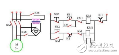
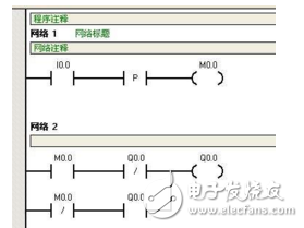
Although the PLC ladder diagram control program has similarities with the relay contactor control circuit, it is not an absolute one-to-one correspondence. Because the structure and working principle of PLC are different from the relay contactor control circuit, there are some differences between the ladder diagram control program and the relay contactor control circuit.
(1) PLC uses ladder diagram programming to simulate the representation method of the relay contactor control system, so the components in the ladder diagram also follow the name of the relay contactor control system, which is called "(soft) relay" . However, the "soft relay" in the ladder diagram is not a real physical relay. Each "soft relay" is a "bit register" in the PLC memory. There are two opposite states. When the state of the corresponding bit is "1", it means The relay coil is "powered", and when the state is "0", it means the relay coil is "powered down", so it is called a "soft relay". Using "relay" to indicate the components in the PLC can design the ladder diagram program in the form of a relay contactor control system.


(2) The "current" flowing in the ladder program is not a real physical current, but a "energy flow", which can only flow according to the rules of "from left to right" and "from top to bottom". "Power flow" does not allow reverse flow. When "power flow" arrives, the corresponding coil is energized. In fact, "energy flow" is just a visual representation when the output execution conditions are met in the user program operation. The rules of the "energy flow" flow direction are stipulated in order to comply with the sequence of PLC scanning being "from left to right" and "from top to bottom". However, the current in the relay contactor control system is a real physical current, which can be measured with an ammeter, and its flow direction can also flow freely according to the actual situation of the external power supply.
(3) The normally open and normally closed contacts in the ladder program are not actual physical contacts. They only reflect the state of the corresponding bit in the input, output image register or data register corresponding to the state of the physical switch on site. In the PLC, the normally open contact is considered to be a "read" operation on the state of the bit register, while the normally closed The contact is to "invert" the bit register.
(4) The coil in the ladder program is not an actual physical coil, and it cannot be used to directly drive the actuator of the field component. The status in the output coil will be directly transferred to the corresponding bit of the output image register, and then use the status "1" (high level) or "0" (low level) in the output image register bit to control the output circuit Corresponding circuit, and after power amplification, to control the PLC output device (relay, transistor or thyristor), and then make its contacts open and close to control the actuator of the external field components.
(5) When compiling the ladder diagram program, the contacts of the PLC internal relay can be called unlimited times in principle, because the bit state in the storage unit can be read repeatedly; and the number of relay contacts in the relay contactor control circuit is determined by the relay It is determined by the structural form, and therefore will be fixed as the structural form is determined, and the number is limited. It should be particularly emphasized that in PLC, the coil can only be called once in the same ladder program under normal circumstances. Therefore, it is necessary to avoid repeated use of coils with the same address number (duplicate coils will cause uncertainty in the output results).
Ac Remote,Universal Ac Remote,Aircon Remote Control,Air Conditioner Remote
Full Industrial CO.,ltd. , https://www.iotaindustrial.com