With the development of information technology, the application system that supports the touch operation of the graphical interface and the real-time operating system has been increasingly applied to aerospace, military, consumer electronics, communications equipment and other fields. The mC/OS-II operating system is a preemptive, real-time operating system (RTOS). Due to its core detachability and strippability, it has a wide range of applications in real-time control. It not only reduces the unreliable factors caused by system hardware design defects, but also enhances the real-time control of the system, and further enhances the performance of the ARM control system from the software aspect. In addition, the new version of mC/OS-II has passed the FAA certification and is suitable for applications in the field of embedded industrial control with high real-time requirements, such as military fighter aircraft, attack aircraft, and fire control systems that are currently widely used.
Supporting graphical interface operation (mC/GUI) is a popular human-computer interaction system. It can provide a friendly human-computer interaction platform, making the microprocessor a tool that most people can use and accept. Unlike PCs, since mC/OS-II is basically a "black box" operating system, the control and development of human-machine interfaces requires more complicated programming techniques and timing control techniques. ARM7 embedded real-time control system has higher requirements for mC/GUI, including light weight, low resource consumption, high performance, high reliability, and configurability. Therefore, how to combine the ARM7, mC/GUI, mC/OS-II, touch screen driver, and application programs together to run on the ARM7 and complete the tasks that the user wants to achieve has become an issue in the development of embedded operating systems. Key technologies.
mC/OS-II embedded operating system portingmC/OS-II is the kernel of the operating system. The main task is to complete the scheduling and synchronization between multiple tasks and to coordinate the hardware sources without conflict. Compared with other embedded operating systems, it has the characteristics of transparent system, removable and simple interface. The following is a brief description of how to port and modify the operating system on the S3C44B0:
(1) Re-edit the OS_CPU.H file
a) Define data types: mC/OS-II does not use data types related to processor types such as short, int, and long in C language, but instead uses a highly portable data type, which is both intuitive and easy to transplant;
b) Defining the type of stack growth and the mode in which ARM runs: Although the ARM processor supports both the upward and downward growth of the stack, the compiler ADS only supports the stack from top to bottom and must be full-decrement stack. , so the value of the constant OS_STK_GROWTH used to define the stack growth mode in the file is 1;
c) Declaration of external functions: As in the mC/OS-II.h header file, some functions to be ported have been declared, including: OSTaskStkInit(), OSIntCtxSw(void), OSStartHighRdy(void).
(2) Modify the OS_CPU_C.C file
a) task stack initialization function OSTaskStkInit(): Before writing the task stack initialization function OSTaskStkInit(), the stack structure of the task must be determined according to the structure and characteristics of the processor;
b) Hook function: mC/OS-II presets some hook functions (such as OSTimeTickHook) for the user to write their own code in the system function. These functions can be all-empty when transplanting, and can be added according to the user's needs.
(3) Write the OS_CPU_A.S file. a) On/Off interrupt function: In the ARM7 processor core, it can be implemented by changing the corresponding control bit in the program status register CPSR;
b) OSStartHighRdy (void): The OSStart() function calls OSStartHighRdy() to start the task with the highest priority among the ready-to-go tasks;
c) OS_TASK_SW(void): μC/OS-II completes the task scheduling by calling OSSched() function. OSSched() first loads the address of the highest priority task to OSTCBHighRdy, and then executes task-level tasks by calling OS_TASK_SW(). Switching, OS_TASK_SW mainly completes the protection of the site, completes the tasks used, and restores the site;
d) OSIntCtxSw(void): OSIntExit() performs a task switching function in the interrupt service routine by calling OSIntCtxSw().
e) Clock tick function: In this migration, only ARM's IRQ interrupt is used. Because the interrupt systems of different ARM chips are not exactly the same, it is impossible to write out the interrupt and beat transplantation code common to all processors using the ARM core, but this is the focus of the follow-up task management needs to be handled by the operating system, OSTIckISR The implementation of the code see the list of procedures.
List of procedures OSTIckISR()
OSTickISR
STMFD SP! , {R0-R3,R12,LR}
BL OSIntEnter
BL user_function ; Invoke user
Processed interrupt handler
BL OSIntExit
LDMFD SP! ,{R0-R3,R12,LR}
This article uses a fixed reference voltage mode, in the driver development process, you need to pay attention to the timing characteristics of the clock, input and output. First check if PENIRQ is low. This bit will be low only if the touch screen has contact. Use software to simulate three-wire serial transmission timings on DIN, DOUT, and DCLK, and serially read the control word of the read X or Y coordinate value to ADS7843. Then read the coordinate value from the corresponding function to obtain the coordinate value. The source program is as follows:
Int TOUCH_X_MeasureX(void)
{
X=ReadTouchXY(CHX);
Return X;
}
Int TOUCH_X_MeasureY(void)
{
Y=ReadTouchXY(CHY);
Return Y;
}
Among them, ReadTouchXY () function through TOUCH_X_MeasureX (void), TOUCH_X_MeasureY (void) read the corresponding coordinates of the X, Y axis voltage value, and sent to the main control program for coordinate transformation, to get the current touch screen press position.
Int ReadTouchXY(unsigned char
Command)
{
//According to the command parameter, perform X, Y touch point selection, debounce, position calculation, etc.
Return ack;//Return to touch screen corresponding bit
Set value
}
mC/GUI and interface with operating system
The mC/GUI is a program running on the operating system. It needs to coordinate with the operating system and coordinate with various input/output devices. That is, the input device receives user requests and the output device sends microprocessor processing results. . Therefore, the mC/GUI interface mainly includes two interfaces: an interface with the operating system and an interface with the input/output device, which is also a key problem to be solved in the process of migrating the mC/GUI. When mC/GUI is combined with mC/OS-II to solve the problem of mutual exclusion of resources through locking and unlocking, the process is to set GUI_X_Lock() at the entrance of the key area to obtain the exclusive access right, and use it at the exit after use. GUI_X_Unlock() is set to allow resources to reach the mutual exclusion of multiple GUI tasks accessing the same data within the critical area.
In the process of migrating mC/GUI to mC/OS-II, you need to use the resources of the operating system to implement the functions required by the GUI. That is, μC/GUI is implemented using the time management, task management, and resource sharing mechanisms provided by μC/OSII. The corresponding function in the specific implementation of the following functions to redefine:
(1) Time function
GUI_X_Delay () / / return after the specified period of time delay
GUI_X_ExecIdle() // Non-blocking function call of the window manager
GUI_X_GetTime() // returns the current
System time in milliseconds
(2) Kernel interface functions
GUI_X_InitOS() // Initialize the kernel
Interface module
GUI_X_GetTaskID() // returns a
Current task/thread unique 32-bit identifier
GUI_X_Lock() //Lock the GUI
GUI_X_UnLock() // Unlock GUI
GUI_X_Log() //Return debugging information
(3) LCD bottom driver
To enable mC/GUI to run on the target system, the mC/GUI must first be configured and modified, that is, ported. Migration mainly refers to the macro definition in the configuration header file to be modified according to specific conditions, including LCD macros and LCD controller macros. When using the mC/GUI library function, the header file “gui.h†must be called before the main function and be modified as necessary. It is worth noting that GUI_SUPPORT_TOUCH must be set to 1 in the predefined statement of this file. If you need to display Chinese on the screen, in addition to adding Chinese fonts to the project, you also need to set GULDEFAULT_FONT to &GULFontHZ12. HZ12 represents the Chinese font used. If you need to use Chinese in mC/GUI controls, you also need to make corresponding changes in the control's predefined statements. Since the ARM7 chip S3C44B0X integrates an LCD controller, the LCD bottom layer driver is mainly designed with the parameters related to the LCD screen and its special control registers, mainly including the following parameters and registers:
#dene SCR_XSIZE (640)
//LCD horizontal size
#dene SCR_YSIZE (240)
//LCD vertical size
#dene LCD_XSIZE (640)
//LCD horizontal resolution
#dene LCD_YSIZE (240)
//LCD vertical resolution
#define ARRAY_SIZE_COLOR (SCR_XSIZE/1*SCR_YSIZE)
//LCD horizontal and vertical ratio
#define HOZVAL_COLOR (LCD_XSIZE*3/8-1)
//LCD horizontal byte size
#dene SCR_XSIZE (640)
//LCD horizontal size
#dene SCR_XSIZE (640)
//LCD horizontal size
The definition of the register is defined according to different microprocessors and LCD colors, sizes, etc. Here is an explanation of S3C44B0X:
rLCDCON1 = (0) | (2 "" 5) | (MVAL_USED "" 7) | (0x3 "" 8) | (0x3 "" 10) | (CLKVAL_COLOR "" 12);
rLCDCON2=(LINEVAL)
| (HOZVAL_COLOR "" 10) | (10 "" 21);
rLCDSADDR1 = (0x3 "" 27) | (((U32) frameBuffer" "22) "21" | M5D ((U32) frameBuer" "1);
rLCDSADDR3= (LCD_XSIZE/2)|(((SCR_XSIZE-LCD_XSIZE)/2)"9";
Development of applications under embedded operating systems
Developing ARM7-based applications under the embedded operating system is mainly to divide tasks, and establish different priorities according to the urgency of each task. The following describes principles and examples of task division:
Task division principle
When decomposing a software system into parallel tasks, the asynchronism of functions in the system is mainly considered. By analyzing the transformations in the data flow graph, it is determined which transformations are parallel and which transformations are essentially performed sequentially. In this way, a transformation corresponds to a task, or a transformation includes several tasks, and the following principles should be followed:
â— I/O dependencies: due to I/O speed limitations, the program that operates on it should be a separate task;
â— Time-critical: Separating time-critical functions into independent tasks and giving high priority;
â— Calculation function: The calculation function should occupy more CPU time and should be given a lower priority.
â— Functional cohesion: a group of closely related functions that make each function share resources or drive the same event;
â— Time Gather: Tasks that will be completed at the same time, even if the functions are not related, constitute an independent task;
â— Periodic execution function: Each function executed in the same cycle constitutes one task, and high frequency gives high priority.
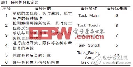
ApplicationsThis article takes the actual project as an example for analysis. In this project, the touch screen is used as the input device and the system detects the output window. Through the controller's embedded mC/OS-II operating system and mC/GUI, the function of the corresponding button command can be completed. The background of the specific task to complete a variety of interrupts, calculations, communications and other functions. Therefore, the task division and definition as listed in Table 1 were performed.
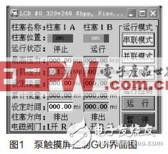
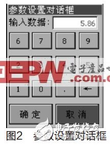
The touch screen application can be written based on the actual use of the touch screen, but it should pay attention to the modular programming concept when writing so that it can be ported to related applications as an input platform. This article has written a pump control system as an example of a touch screen application design. The operating interface of the control system written using the graphic software mC/GUI is shown in Fig. 1. When using the touch pen or finger to directly click on the editable button controls (such as the highest pressure, setting flow and setting time), the pop-up parameter input The dialog box is shown in Figure 2. The mC/GUI design has a modular feature and includes different layers in different modules. For example, the LCD driver includes all interfaces with the LCD. Similarly, the mC/GUI also provides a universal touch screen application program interface (API) that can be conveniently used by an application program by adding its library to the project.
The development of application software on the mC/OS-II real-time operating system and ARM platform has become a hot spot in the modern industry, which can greatly reduce the time and task difficulty in the preparation of software programs, improve the independence of each module, shorten the development cycle, and the system Better stability, portability, and maintainability. This article takes the actual project as the application background. The ARM7-based touch screen (mC/GUI)-based real-time operating system (mC/OS-II) has a good man-machine interface and is well-developed for driving, controlling, displaying, detecting and calculating. Features, support stand-alone and network control operation.
Antenk D-Sub,D-Shaped Connectors Solutions offer a broad range of higher reliability D-Sub connectors.
Antenk's D-Sub product line is designed for applications that require a rugged, robust I/O connector system with various styles and mounting options. All are used in a variety of industries including computer, industrial, medical, and military markets.
Antenk High-Density D-Sub Connectors
Available in cable mount options including crimp & solder cup and the board mount options including Dip Solder, Wire Wrap, High Profile, Right Angle, & Surface Mount (SMT). This comprehensive Antenk High-Density Density D-Sub product offering is available in both stamped & formed and machined contact options.
High density D-Sub connectors, for applications where the best possible contact density is required. Due to the [high" density of the 15, 26, 44, 62 and 78 contacts, this series is ideal for the most modern applications. The insulating body, a monoblock, complies with the UL94 V-0 standard. The contacts are machined and available in several quality classes.
Antenk Solder Type D-Sub Connector
Available in standard and high density versions
Supplied with stamped & formed or screw machine contacts.
Standard contact terminations accomodate up to 20 AWG standard wire
Available with white (nylon) or black (PBT) insulators. Standard shell plating is tin
Antenk D-Sub connectors solder cup machined contacts are manufactured according to the standards MIL-C-24308 and DIN 41652. The standard connectors from Antenk are available in all known versions and sizes. They are available in various version with numerous assemblies. The insulating body, a monoblock, complies with the UL94 V-0 standard. The contacts are machined and available in several quality classes.
Features of Antenk's Solder Cup Standard D-Sub Connector Machined contacts
Solder cup d-sub available in 5 industry sizes/positions
Standard Density (9 pin, 15 pin, 25 pin, 37 pin, 50 pin)
Tin shells have indents to provide grounding and additional retention.
Screw machine contacts offer high reliability. Non-removable contacts.
Optional mounting hardware available.
Materials of Antenk Solder Cup Standard D-Sub Connector Machined contacts
Shell: Steel, tin plated
Insulator: Glass-filled thermoplastic. U.L. rated 94V-O
(260°C process temp)
Machined contacts:
Male pins - Brass | Female pins - Brass
Plating: Gold flash on entire contact
Contact us for other plating options
Features of Solder Cup High Density D-Sub Machined Contacts
Solder cup d-subs in 4 industry sizes/positions
High Density (15 pin, 26 pin, 44 pin, 62 pin).
Approximately 65% more higher density then standard d-sub connectors.
Screw machined contacts offer high reliability.
Metal Shell provides EMI/RFI shielding. Available in 3 clinch-nut options.
Plug shells have indents to provide grounding & additional retention.
Connectors will fit in standard D-sub backshells.
Contacts will accept (28 - 24) gauge wire.
Materials of Solder Cup High Density D-Sub Machined Contacts
Shell: Steel, Nickel plated
Insulator: Glass-filled, PBT Thermoplastic. U.L. rated 94V-O
(230°C process temp)
Machined contacts: Brass, Gold Flash Plated(contact us for other plating options)
9 pin, 15 pin, 25 pin, 37 pin, 50 pin Male Solder Cup Standard D-Sub Connectors Machined Contacts, Solder Cup High Density D-Sub Machined Contacts,Female Solder Cup Standard D-Sub Connectors Machined Contacts
ShenZhen Antenk Electronics Co,Ltd , https://www.antenkelec.com