1. Throttle position sensor function, classification and identification
(1) Effect
Throttle position sensor is one of the most important sensors in automotive electronic control system. It is mainly used for electronic fuel injection system and electronically controlled automatic transmission system. The throttle position sensor is installed on one end of the throttle shaft on the throttle body to detect or monitor the opening degree and the speed of the throttle opening, and converts the position signal into an electric signal and inputs the electronic control unit. Used to determine various conditions of the engine to control different fuel injection and ignition timing. In cars equipped with electronically controlled automatic transmissions, the throttle position sensor signal is the main signal for transmission shifting and torque converter lockup.
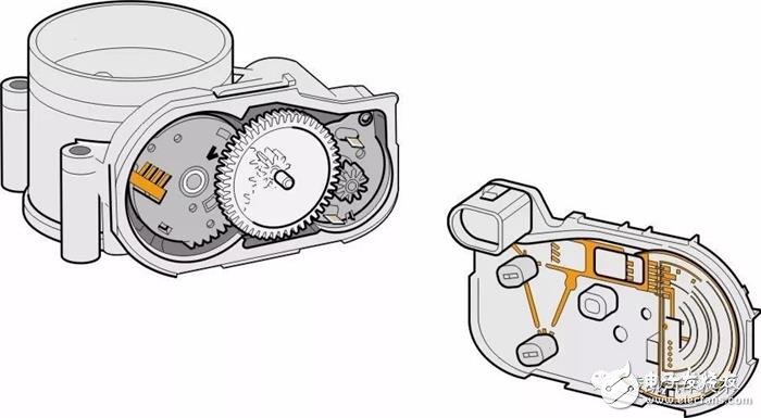
(2) Throttle position sensor type
The conventional throttle control throttle equipped with throttle position sensor, according to the overall structure is divided into contact switch type, sliding resistance type, idle switch and sliding resistance integrated integrated. The throttle position sensor used in the new intelligent electronic throttle valve control system is commonly known as double sliding resistor type and linear double Hall type.
At present, the throttle position sensors mainly used in engine electronic control systems include Hall element type and double sliding resistor type. Toyota's Camry, Corolla, etc. use the Hall element type; Nissan Teana and GM Excelle use dual sliding resistors.
2. Hall throttle position sensor
(1)Structural principle and installation position
The 2016 Toyota Camry Hybrid (Engine Model 6AR-FSE) uses a non-contact dual-Hall element throttle position sensor. Its structure is shown in the figure below. It is mainly composed of a Hall element and a magnet, wherein the magnet is mounted on the throttle shaft and can rotate around the Hall element.
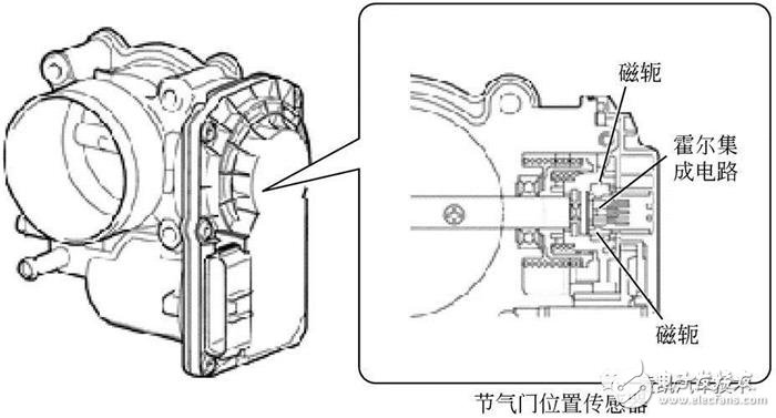
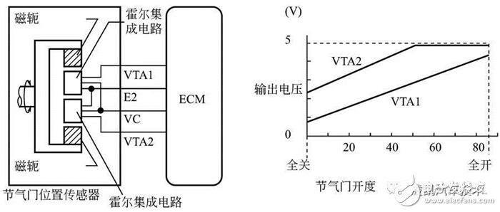
Hall-type throttle position sensor control circuit and signal output characteristics as shown above. When the throttle opening degree changes, the magnet rotates with it, thereby changing the relative position with the Hall element. The Hall IC is surrounded by the yoke. The Hall IC converts the changes produced by the magnetic flux into electrical signals and outputs them to the ECM in the form of a throttle position signal.
The throttle position sensor has two sensor circuits: VTA1 and VTA2, each emitting a signal. VTA1 is used to detect the throttle opening, and VTA2 is used to detect the fault of VTA1. The sensor signal voltage is proportional to the throttle opening and varies from 0 to 5V and is sent to the ECM terminals VTA1 and VTA2.
When the throttle is closed, the sensor output voltage decreases; when the throttle is opened, the sensor output voltage increases. The ECM calculates the throttle opening based on these signals and controls the throttle actuator to respond to the driver input. These signals are also used to calculate air-fuel ratio corrections, power boost corrections, and fuel-cut control.
(2) Circuit connection
The 2016 Toyota Camry Hybrid throttle position sensor circuit is shown below.
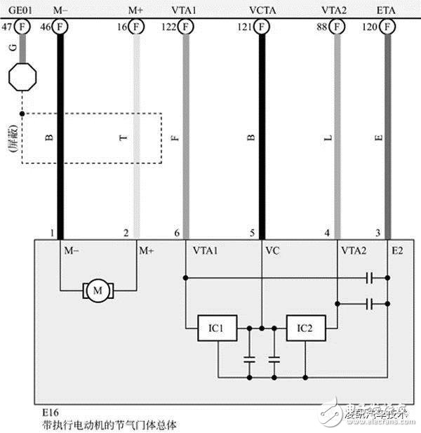
The throttle position sensor is integrated in the throttle body assembly E16. E16 has 6 pins. Pins 1 and 2 perform motor control ports for the throttle. Pins 6 and 4 respectively output throttle position signals VTA1 and VTA2 to 122# and 88# of engine control unit port E81(F). Pin 5 is the VCTA 5V reference voltage supplied from the engine control unit 121#; pin 3 is grounded through the engine control unit 120#.
(3) Detection
1 Check sensor power supply: Disconnect the throttle body connector E16 and use a multimeter to measure the voltage between E16/5 and E16/3, which should be 4.5~5.5V. Otherwise, check the ECU power circuit. If the ECU power circuit is normal, replace the ECU.
2 Check the signal voltage of the sensor: Connect the fault diagnostic device, turn on the ignition switch, step on the accelerator pedal, and read the throttle position sensor data VTA1 and VTA2 readings. The values ​​should be in accordance with the following table.
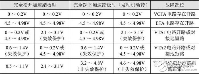
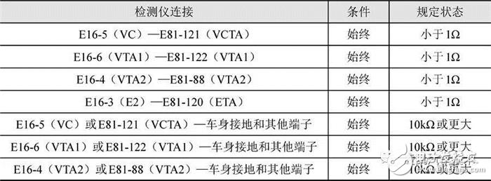
3 Check the sensor wiring harness and connector: Disconnect the throttle body connector E16 and the ECM connector E81 of the engine control unit and check the resistance value between the connectors or between the connector and the body ground as shown in the following table. . The resistance value should be as shown in the table, if it does not meet the replacement or inspection harness.
3. Sliding resistance throttle position sensor
(1) Structure
Slide resistance throttle position sensor, also known as linear output throttle position sensor, variable resistance throttle position sensor, potentiometer throttle position sensor. Currently dual variable resistance throttle position sensors are being used in large numbers in automobiles.
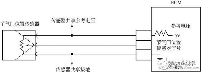
The sliding resistance type throttle position sensor is a three-wire type sensor in which two pins are located at both ends of the resistance, and are supplied by the engine ECU as a power terminal and a grounding terminal with a voltage of 5V, and the third pin is connected to the sliding contact. The throttle shaft and the contact (or contact) are linked. When the throttle is rotated, the sliding contact can move on the resistance, causing a change in the sliding contact potential. The throttle position signal is converted into a voltage value by using a change in the resistance. As shown below. Because this voltage changes linearly, it is also called a linear output type throttle position sensor. Based on this linear voltage value, the ECU senses the throttle opening and allows the ECU to correct the fuel injection.
(2) Sensor detection
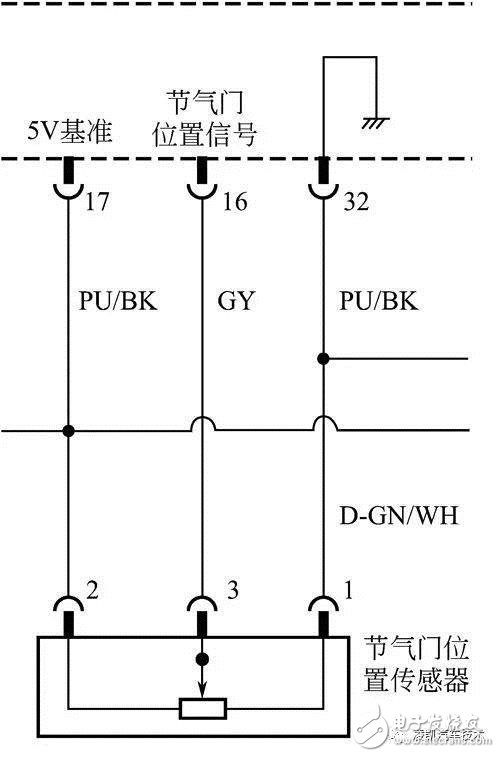
2013 Buick Excelle car throttle position sensor circuit as shown below. The engine control module provides a 5V reference voltage circuit to the throttle position sensor and provides ground to the low reference voltage circuit. The signal voltage provided by the throttle position sensor varies with the throttle opening. Throttle position sensor signal voltage is less than 0.5V during idle operation. Throttle position sensor voltage is generally close to 0V at idle but may be as high as 0.5V. In the full throttle (WOT) season, the valve position sensor voltage should be increased to more than 4V.
Throttle position sensor detects as follows:
1 Turn off the ignition and disconnect the harness connector on the throttle body assembly.
2 Measure whether the resistance between the 5V reference terminal 2# and the low voltage reference terminal 1# of the throttle position sensor is between 5.0 and 5.3kΩ. If the resistance is not within the specified range, replace the throttle body assembly.
3 Measure the resistance between throttle body signal terminal 3# and low voltage reference word 1#. Detect throttle sensors in full range. The resistance should vary between 2.5 and 6.8kΩ without any peaks or valleys. If the resistance is not within the specified range or is unstable, replace the throttle body assembly.
4 Connect the applicable terminal of the throttle sensor with a voltage of 5V and ground, and check the voltage between the signal terminal and the low voltage reference terminal. Detect throttle sensors in full range. The voltage should vary between 0.6 and 4.7V without any peaks or valleys. If the voltage is not within the specified range or is unstable, replace the throttle body assembly.
(3) Dual variable resistance throttle position sensor
Two sensors of the dual variable resistance throttle position sensor are generally assembled and installed, and can be recognized in time when one sensor fails, which increases the reliability of the system. From the relationship between the output signals of the two sensors, there are two types, inverting and in-phase. The in-phase can be divided into two kinds: linear change with same slope and linear change with different slope.
The BOSCH dual variable resistance throttle position sensor structure and internal circuit are shown in the figure below.
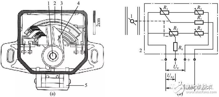
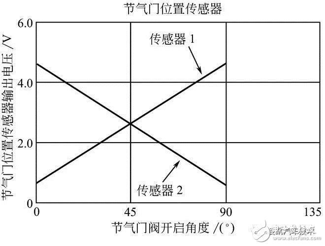
The dual-track throttle position sensor on the throttle shaft is used to monitor the precise opening of the throttle. The slide of the throttle position sensor (two potentiometers) is coaxial with the throttle. When the throttle is rotated, the potentiometer slides rotate synchronously. When a 5V operating voltage is applied, the changed resistance is converted into a voltage output signal. The output voltage of the potentiometer changes with the position of the throttle valve, so that the control unit can accurately know the opening of the throttle valve. Since the two potentiometers are installed in reverse phase, when the throttle position changes, both signal voltages change linearly, one of which increases while the other decreases. The following figure shows the output characteristics of the throttle position sensor in Nissan.
The Nissan Teana vehicle dual variable resistance sensor circuit is shown below.
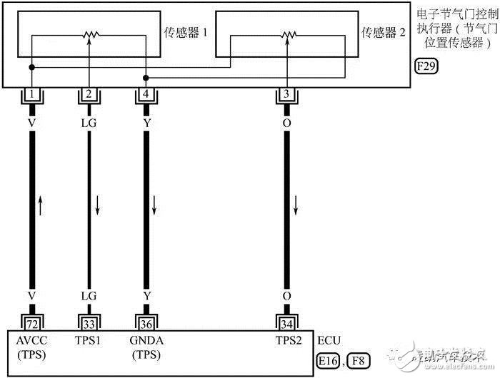
The engine control unit ECM provides 5V reference voltage to the sensor 1# terminal through the 72# terminal; the sensor 4# terminal is grounded through the 36# terminal of the electronic control unit. The TPS1 and TPS2 throttle position signals output from sensors 2# and 3# are sent to the 33# and 36# of the engine control system, respectively.
The inspection of dual variable resistance throttle position sensors (taking Nissan Teana as an example) is as follows:
Turn on the ignition switch, change the shift lever to D range (A/T) or 1 range (M/T), check the ECM's port 33 (signal at throttle position sensor 1#), 34 (sections) using the multimeter's voltage block. The signal at the 2# end of the valve position sensor) is the voltage between the accelerator pedal and the ground in different states. The inspection result should comply with the following table. If not, replace the throttle body assembly.

4. Switching electric shock throttle position sensor
(1) Structure principle
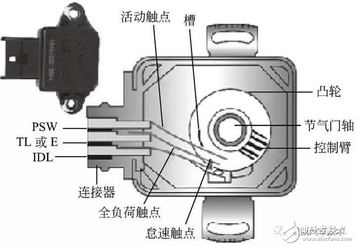
The switch contact type throttle position sensor is also called a throttle switch. It has two contacts, IDD and PSW. In the following figure, there is a cam control movable contact (TL or E) coaxial with the throttle valve, which opens and closes the two switch contacts with the state of the throttle. When the throttle valve is in the fully closed position, the idle contact IDL is connected with the movable contact TL or E, and the ECU determines that the engine is in an idling condition according to the idle speed signal, thereby controlling the engine operation according to the requirements of the idle condition. When the throttle is opened, the idle contact opens, and the ECU performs the engine running control from the idle state to the small load in accordance with this signal; the large load contact is always in the range from the fully closed position to the middle and small opening of the throttle. Disconnected state. When the throttle is opened to a certain angle, the large load contact is connected to the movable contact TL or E, and the ECU sends a signal that the engine is in a full load operating condition, and the ECU performs full load enrichment control according to this signal.
Wifi 5 Wireless Router,5Gz Wifi Router,Wi-Fi Routers For The Home,Lte Modem Router
Shenzhen MovingComm Technology Co., Ltd. , https://www.movingcommiot.com