Many engineers know that switching power transformers can be shielded by adding a winding between the primary winding and the secondary winding when grounding, but what is the mechanism? Some engineers don't understand it well.
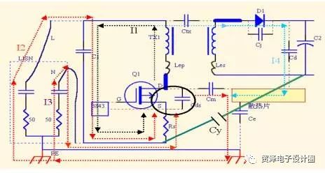
The EMI propagation path is as follows

The stray capacitance Cm/Cd of the Mosfet/Diode to the heat sink; and the stray capacitance Ce of the heat sink to the ground are coupled to the LISN to be captured by the sampling resistor.
The general response in the absence of shielding is to indirectly pass a Y capacitor (472) at the ground of Rs and the ground of C2.
Its role is twofold, one is the noise current generated by the Mosfet action and stringed to the secondary side of the transformer (such as I4), providing a low impedance loop to reduce the current to ground. The second is to provide a low-impedance loop for the noise current generated by the secondary side Diode and connected to the primary side of the transformer, thereby reducing the current flowing through the LISN.
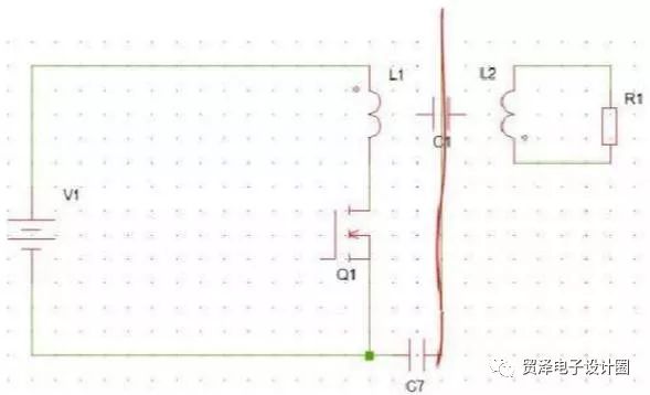
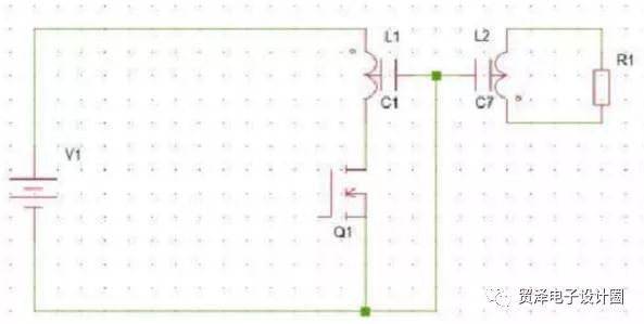
How to suppress EMI transmission after adding shielding? As shown below

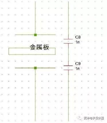
This connection is to divide C1 into two, the primary side is shielded, the secondary side is shielded, and each is grounded, that is, it is divided into two capacitors, and grounded at the intermediate point. Bypass the primary noise. Adding a metal plate to the primary and secondary can change the primary and secondary capacitors into two.

This primary noise can be bypassed from the metal plate to the ground.

Winding and comparison of interlayer shielding of high frequency transformer
Method for adding high frequency transformer
1. Wrap a long strip of copper or aluminum foil between the primary winding and the secondary winding of the power transformer, wrapping more than one turn, but the first end can not touch (short circuit), and the grounding is led out by welding or wrapping. It has an insulating layer inside and outside, and a secondary winding around it.
2. Wrap a layer of enameled wire with a diameter of 0.1 to 0.3 around the primary winding and the secondary winding of the power transformer, with the other end leading to the ground. It also has an insulating layer inside and outside.
The shield leads to a reference point at which a line is to be grounded, ie, the potential. Conventional shielding is done between the primary and secondary windings. Regardless of whether it is the outermost layer or the inner winding, it is necessary to pay attention to the shielding: when the winding is wrapped with copper foil, the overlap of the copper foil head and tail needs to be insulated. The reason is very simple: if the insulation is not insulated, the overlapping is a short-circuited coil!
Difference between wirewound shielding and copper foil shielding in high frequency transformers
In addition to the difference in the process of the high-frequency transformer, the shielding effect of the wire shielding and the copper foil shielding is similar. It is not necessarily good to use it in a specific power supply. As for why wire shielding, there are many factors to consider, cost, efficiency, etc. Another point is that the wire shield can be designed more flexibly, such as the starting point, end point, and winding direction of the shield, which will have a practical effect on the shielding effect.
The cost of shielding with copper wire will be low, it can be automated, many companies have automatic machines; and the consistency of products produced with copper wire shielding is very good during EMI testing;
Some shielded copper wires are used for supplemental windings to adjust the internal winding capacitance. It is convenient to adjust the number of turns, which is commonly used in switching transformers.
Diesel Pressure Sensor,Hydraulic Pressure Gauge,Rail Pressure Sensor,Absolute Pressure Transmitter
Shenzhen Ever-smart Sensor Technology Co., LTD , https://www.fluhandy.com