Imagine the way you drive to work this morning: the traffic light turns green, you immediately step on the gas pedal, the car responds quickly in a few seconds and continues to the company. This process seems simple, but in reality, a series of complicated operations have taken place in the car. Let's take a look.
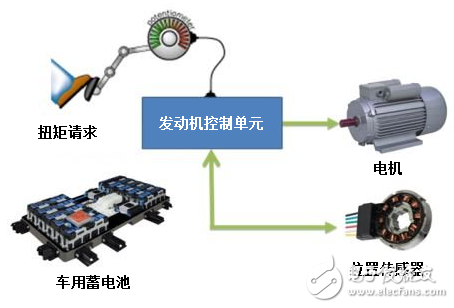
When you step on the pedal, the motor will provide the necessary torque by turning the axle, and then the traction motor drives the vehicle forward. Traction motors (usually three-phase synchronous motors) are controlled by complex circuits, including multiple transistors, motor drives, and protection and feedback controls. The feedback control signal is emitted by the motor position sensor (see Figure 1) in the form of an analog angular output signal (note that all real world signals are analog). Continuous analog signals are converted to digital domains by means of an analog-to-digital converter (ADC). Ideally, you can decompose a continuous analog signal into an infinite number of digital steps, but in the real world, the analog signal quantization of an ADC is a finite number of steps, and the resulting error is called quantization error. The terms "precision" and "resolution" are used here.

Figure 1: Typical system block diagram of the vehicle motor control system
Precision
Take a 12-bit shaft angle digitizer (RDC) as an example. The rotary shaft rotates one revolution and the converter outputs 212 = 4096 digital codes. In motor control, the step size is usually defined in arc minutes or arc seconds. Once 60 minutes, one turn 360 degrees. Therefore, there are 360 ​​& TImes on one lap; 60 = 21600 arc points. Since there are 4096 digital codes, each partition is divided by = 21600/4096, that is, 5.27 arcs. The 5.27 arc minute corresponds to a least significant bit or 1 LSB. Therefore, even if the input angle (continuous signal) is 100% accurate, the output digital code cannot move more than 1 LSB (or 5.27 arc minutes) before the next code. The RDC takes into account the offset, gain, and linearity error factors when specifying this precision value. For reference, the typical accuracy specification for a brushless resolver is 10 arc minutes. The typical error of the entire analyzer system, plus the sensor and conversion error, is approximately ±15.273 arc minutes (analytical sensor is 10 arc minutes, compared to +5.273 arc minutes in my example). These numbers will help us choose the right sensor solution for our system.
Resolution
So what is the resolution? The "12-bit" resolution refers to 212 different output codes in a 360-degree angular rotation. The actual resolution is only the number of bits available at the RDC output; note that not all bits are noise free. Effective resolution is the true "useful" bit in analog-to-digital conversion where signal noise is taken into account. These are the effective number of bits (ENOB). ENOB is often confused with the resolution described in the product data sheet.
What does 1 LSB mean?
So far, we have discussed the definition of precision and resolution. Now let's apply this knowledge to a system where accuracy and resolution are usually in LSBs. Do you want to know the meaning of LSB in the system environment? First, let's look at the conversion value of 1 LSB relative arc and degree in the field of motor control. The following takes 12 and 10 as an example:
Of the 12 bits, 1 LSB is equal to:
1LSB = 360 ÷ 212 = 0.087 degrees = 5.27 arc minutes = ± 2.64 arc minutes = ± 0.04395 degrees
Similarly, in 10 bits, 1 LSB is equal to:
1LSB = 360 ÷ 210 = 0.351 degrees = 21.09 arc minutes = ± 10.54 arc minutes = ± 0.1757 degrees
in conclusion
Is it a very interesting thing to understand the deeper principles behind car operation? Accuracy and resolution are the basis for choosing the right sensing solution for your specifications. When the accuracy is better than the resolution, the transfer function of the converter can be precisely controlled by the number of resolution bits.
Please leave a comment below or visit the Texas Instruments Online Community Car Forum to discuss rotating position sensing with everyone.
other information
Read the Analog Application Journal article "Design Considerations for Shaft Angle Digitizers in Electric Vehicles."
To learn more about resolver sensing in industrial applications, read the white paper "Electrical Design Considerations for Industrial Resolver Sensing Applications."
Learn more about electric vehicle design in the first and second parts of this EDN article series.
Quickly start a resolver-based rotary position sensing design with TI Design - Automotive Resolver to Digital Converter Reference Design (TIDA-00796) for safety applications .
Download these application guides:
“PGA411-Q1 PCB Design Guideâ€.
"PGA411-Q1 Troubleshooting Guide".
"PGA411-Q1 Software Developer's Guide."
"PGA411-Q1 uses any host system for step-by-step initialization."
Â
New Arrival or New Style Disposable ecig have a completely enclosed design, reducing the need for charging and replacing cartridges. The no-charge design also reduces the occurrence of faults. It is understood that with rechargeable e-cigarettes, each cartridge needs to be charged at least once and the battery efficiency is extremely low, while the design of disposable ecig can solve this problem very well.
New Arrival Disposable E-Cigarette,New Arrival Mini E Cigarette,New Arrival Electronic Cigarette Customizing,Rechargeable E Cigarette
Shenzhen E-wisdom Network Technology Co., Ltd. , https://www.healthy-cigarettes.com