Recently engaged in PM2.5 testing. The PMS7003 sensor is used. BUT, has not been touched before. Need to go step by step. First test whether the serial port is communicating.
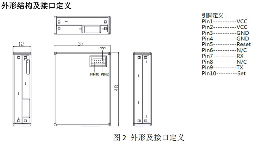
First, look at the interface definition of PMS7003
Second, 485 interface circuit diagram
The 232 communication manual will be very clear. Then because of the need to connect 485 with the DM368 part. So you need a max3485 chip.
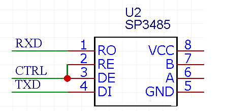
When the microcontroller wants to send data, the control CTRL is high and the data is sent out through the TXD.
When the microcontroller is to receive data, the control CTRL is low and the data is received back via RXD.
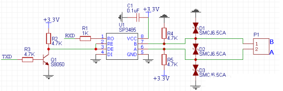
The automatic transceiver circuit does not use the MCU pin CTRL. When the data comes in, the data will automatically pass through the RXD to the MCU. When the data needs to be sent, it will be sent out automatically through the TXD. That is, only need to connect the RXD and TXD pins of the MCU, and it is not necessary to use the MCU pin to connect the DE RE pin of the 485 chip.
Third, UART test
Connect it to the computer with a 232/485 converter and a USB to serial data cable.
Because the PMS7003 sensor sends data whenever it is powered up. So configure the serial port debugging tool to the port number and select the hexadecimal display. You can see the relevant data output.
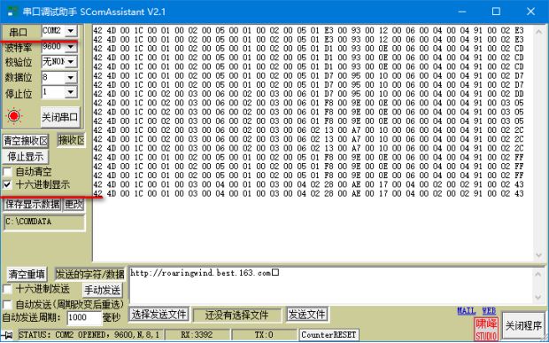
It is now proven that the serial port is open and then the sensor is good. The next step is to look at the sensor manual, and then how to write the test code under the microcontroller and Linux.
The things to note here are:
Pin2 - RE#: Receiver output enable (active low)
Pin3 - DE: Drive output enable (active high)
Is the input or output, configure high level or low level, you must confirm it.
Then there is the 485 NP pin to be connected, otherwise the received data is wrong.
If you are really forced, turn the NP over and try it out...
Shenzhen Happybate Trading Co.,LTD , https://www.happybateprojectors.com