uF grade ceramic capacitor 1Khz, nF level of several hundred KHz, pF grade is not easy to measure. In short, the frequency is as low as possible when the L and R and the table are sufficiently accurate, reducing the effects of line, pin inductance and skin effect.
Capacitor "200pF" 100KHz parallel
Capacitance ≥ 1μF (non-electrolytic capacitor) 100Hz parallel
Capacitance ≥ 1μF (electrolytic capacitor) 100Hz series plus DC offset, such as 1V
Inductance <100nH" 100KHz series depending on the situation plus DC offset
Inductance ≥1H100Hz parallel measurement level AC should be low, such as as low as 50mV.
Resistance <100Ω1kHz series
Resistance ≥10KΩ1KHz parallel
Other component tests are tested using general test conditions: 1V for level AC, 1KHz for frequency, and automatic measurement mode.
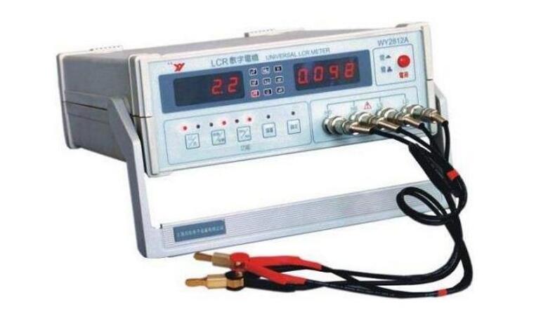
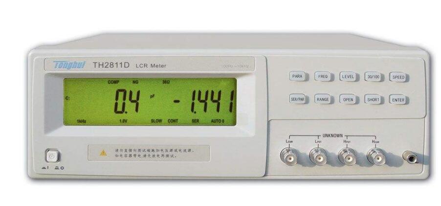
LCR is a sand meter that accurately detects the parameters of various components. It is often used to wake up devices such as inductors, capacitors, resistors, etc., and has the advantages of simple operation and low cost. When using LCR to measure the inductance, you may encounter such a problem. Which one should be chosen for the series and parallel modes?
Series and parallel test buttons for the bridge
Low string height and small impedance devices use series mode to calculate high precision. For example, the impedance is less than 1K for series connection, 1K to tens of K strings for parallel connection, or it is recommended to use series connection. The large-impedance device uses a parallel mode to calculate high precision, and the parallel mode is used when the impedance is greater than a few hundred K or M. That is, the large inductor 200H or the small capacitor is connected in parallel. Small inductors of 2mH or large capacitors are connected in series. In addition, small inductance small capacitors can increase the test frequency to improve the measurement accuracy. In practice, the series mode is used more.
Electrolytic capacitors generally have a low impedance value and are selected in series. If there is still uncertainty, it can be connected in series according to the situation. As the case may be, the DC bias inductor 21H100HZ parallel measurement level AC is low, such as as low as 50mV.
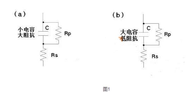
As shown in Figure 1, Figure a is a small-capacity capacitor and Figure b is a large-capacity capacitor.
Since the graph a is a small-capacity capacitor, the impedance is large. At this time, the influence of the shunt resistor RP is much larger than the series resistor Rs, so the measurement should be in the parallel mode. Figure b is a large-capacity capacitor with a low impedance. The impedance after paralleling with RP is less than or much less than the series resistance Rs. At this time, the influence of series resistance RS in the capacitor is much larger than the parallel resistance, so the measurement should be in series mode.
Agilent (HP) recommends:
The total impedance is greater than 10k ohms and is measured using the parallel mode;
The total impedance is less than 10 ohms and is measured using the series mode;
The total impedance is between 10 ohms and 10K ohms measured according to factory recommended measurement requirements.
Nlw-Ecl Sm Fiber,Sm Semiconductor Lasers,Semiconductor Nanowire Lasers,Semiconductor Lasers Silicon Photonics
AcePhotonics Co.,Ltd. , https://www.acephotonics.com