Abstract: This application note describes some of the requirements for Maxim ’s TDM-over-Packet (TDMoP) equipment to work with other manufacturers ’TDMoP equipment. The Maxim TDMoP chips covered in this application note include: DS34T101, DS34T102, DS34T104, DS34T108, DS34S101, DS34S102, DS34S104, and DS34S108.
Interoperability requirements Interoperability is the ability of a system to work with systems from other manufacturers with little or no intervention from a system administrator. With interoperability, the system can provide services to other systems or accept services from other systems, so that systems of different manufacturers can work together normally.
This application note describes some of the requirements for Maxim's TDM-over-Packet (TDMoP) devices to work with other manufacturers' TDMoP devices. The Maxim TDMoP chips covered in this application note include: DS34T101, DS34T102, DS34T104, DS34T108, DS34S101, DS34S102, DS34S104, and DS34S108.
The message data generated by Maxim's TDMoP device may use different header information than the message data generated by TDMoP devices of other manufacturers. In order to achieve the interoperability of Maxim devices, users need to know the type of settings. The setting type can be one of the following options: IP / UDP / RTP / SAToP IP / UDP / RTP / CESoPSN MEF / CESoETH-unstructured (eg MEF / SAToP) MEF / CESoETH-structured lock (eg MEF / CESoPSN ) Each setting has a different header. In order to achieve interoperability, the packet header of Maxim's TDMoP device must have the same format as the packet header of TDMoP devices of other manufacturers. Users need to compare the packet headers of Maxim's TDMoP devices with those of other manufacturers' TDMoP devices. If there are format differences, this application note will demonstrate how to use Maxim's user guide to adjust the packet header of the TDMoP device.
The TDM-over-Packet (TDMoP) section will define the functional description of the TDM-over-Packet module.
The TDMoP message format transmits TDM data on a packet-switched network. The TDMoP chip needs to encapsulate the TDM data as described in Figure 1 into an Ethernet message.
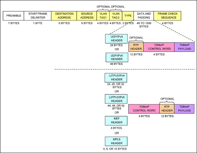
Figure 1. TDM-over-Packet encapsulates incoming Ethernet packets
Table 1. Ethernet message structure
VLAN tagging is as specified in the IEEE® 802.1q standard. Packets tagged with 12-bit VLAN identifiers can construct up to 4096 different VLANs. For those applications where the number is insufficient due to this limitation, VLAN nesting implements a two-layer VLAN tag structure, which expands the ID space of VLANs to 16 million VLANs. Each packet can be sent without a VLAN tag, with one VLAN tag or with two VLAN tags (VLAN nesting). Figures 2 and 3 show a VLAN tag and nested VLAN tag respectively.
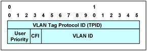
Figure 2. Single VLAN tag
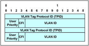
Figure 3. Nested VLAN tags
The VLAN Tag Protocol ID (TPID) is used to identify the VLAN tag. It can be 0x8100 or the value in the vlan_2nd_tag_identifier configuration register. The user priority field is used to specify a priority level for Ethernet packets. The CFI (Specific Format Indicator) field indicates that there is a routing information field. The VLAN ID field uniquely identifies which VLAN the Ethernet packet belongs to. The following figure shows the headers of different protocols. . Figure 4 shows the UDP / IPv4 header structure. Figure 5 shows the UDP / IPv6 header structure. Figure 6 shows the MPLS header structure. Figure 7 shows the MEF header structure. Figure 8 shows the L2TPv3 / IPv4 header structure. Structure Figure 9 shows the header structure of L2TPv3 / IPv6. Figure 10 shows the header structure of Control Word. Figure 11 shows the header structure of RTP. The following table describes the different fields of the header structure. Table 2 describes the different fields of the IPv4 header structure Table 3 describes the different fields of the UDP header structure Table 4 describes the different fields of the IPv6 header structure Table 5 describes the different fields of the MPLS header structure Table 6 describes the different fields of the MEF header structure Table 7 describes the different fields of the L2TPv3 / IPv4 header structure Table 8 describes the different fields of the L2TPv3 header structure Table 9 describes the different fields of the L2TPv3 / IPv6 header structure Table 10 describes the different fields of the control word header structure Table 11 describes the RTP Different fields of the header structure UDP / IPv4 header
Figure 4. UDP / IPv4 header
Table 2. IPv4 header structure
Table 3. UDP header structure
UDP / IPv6 header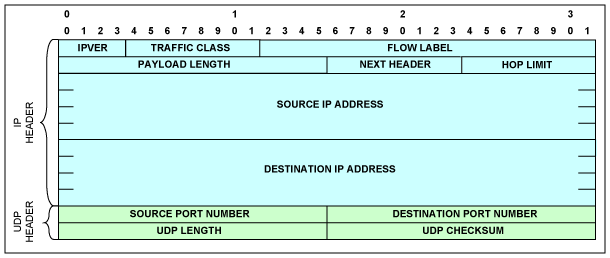
Figure 5. UDP / IPv6 header
Table 4. UDP header structure
MPLS header
Figure 6. MPLS header
Table 5. MPLS header structure
MEF header
Figure 7. MEF header
Table 6. MEF header structure
L2TPv3 / IPv4 header
Figure 8. L2TPv3 / IPv4 header
Table 7. L2TPv3 / IPv4 header structure
Table 8. L2TPv3 header structure
L2TPv3 / IPv6 header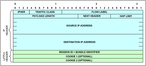
Figure 9. L2TPv3 / IPv6 header
Table 9. L2TPv3 / IPv6 header structure
See Table 8 for L2TPv3 header structure.
Control word
Figure 10. Control word
Table 10. Control word structure
RTP header
Figure 11. RTP header
Table 11. RTP header structure
How to get the packet content of TDMoP devices from other manufacturers There are some softwares that can be used to analyze the Ethernet packet header. This application note uses Wireshark® software. Users can download this free software from. For more information about Wireshark, please see the Wireshark FAQ (English only).
In order to confirm that the user has correctly sent the message with the correct protocol, the user needs to ensure that the two TDMoP system boards from other manufacturers are synchronized with each other. After completing this step, the user needs to use the Wireshark program to capture the message. Figure 12 shows a screenshot of this program.
More detailed pictures (PDF)
Figure 12. Screen capture of the Wireshark program used to analyze the Ethernet packet header
In order to enable intercommunication between systems, the following requirements must be considered: source port number and destination port number message bytes, IP length, UDP length and total length of data bytes Ethernet type source port number and destination port number message classification module Use TDMoP port number to identify UDP / IP of TDM-over-Packet. TDMoIP_Port_Number can be configured to two different values. Although Maxim's TDMoP device has two TDMoIP_Port_Number registers, in many cases, both registers should be configured to the default value (0x085E) assigned by IANA for TDM-over-Packet. The source port number or destination port number contains the binding identification number. The unused field can be set to 0x85E (2142 decimal), which is the user port number assigned by IANA for TDM-over-Packet. As shown in Figure 4, Maxim's device first inserts the source port number, and then inserts the TDMoP destination port number. Figure 13 shows the contents of the User Datagram Protocol (UDP). The source port number is set to 2 and the TDMoP destination port number is set to 0x85E (2142 decimal).

Figure 13. UDP source and destination port numbers
Some manufacturers insert 0x85E as the source port number of UDP and the destination port number of UDP. In this case, the user must configure the system through the preconfiguration menu. The default values ​​of the Maxim software are as follows:
PreConfig Configuration 1. Link Type E1 2. Bundle Number ID Location Port in DST, Bundle in SRC UDP Port 3. UDP Mask 1FFF 4. VCCV OAM Mask [0-4] 0 5. VCCV OAM Value 1FFF 6. MEF Ethernet Type 88D8 7. MEF OAM Type 0 8. TDMoIP Port Number 1 85E 9. Oscillator Type OCXO (Stratum 3E) 10. RTP Clock Source ABSOLUTE 11. Common clock Rate 19440000 12. IP Version IPv4 13. Clock Recovery Smart Statistics Enable 14. One or The second item of the Two Clock Mode One Maxim software menu is used to select the desired Bundle Number ID Location. The second item of the above menu provides the following options:
Bundle Number ID Location 1: Ignore port, Bundle in SRC UDP PORT, 2: Port in DST, Bundle in SRC UDP PORT 3: Port in SRC, Bundle in DST UDP PORT, 4: Ignore Port, Bundle in DST UDP PORT on top In the menu, the default Bundle Number ID Location of the Maxim device is option 2: “Port in DST, Bundle in SRC UDP PORTâ€. In order to make Maxim's equipment interoperable with other manufacturers' equipment, users need to choose option 1, 3 or 4 appropriately. For example, a TDMoP manufacturer's device inserts the Destination port at the Source (SRS) position, and inserts the bound port number at the Destination (DST). If the user selects option 3 in the above menu, the UDP source port Bundle Number ID Location is set to 0x85E (2142 decimal), and the UDP destination port will be 2, as shown in Figure 14. In this way, the TDMoP header of that manufacturer can be matched, so they can interoperate.

Figure 14. UDP source and destination port numbers are reversed from Figure 13
Packet bytes, IP length, UDP length and total length of data bytes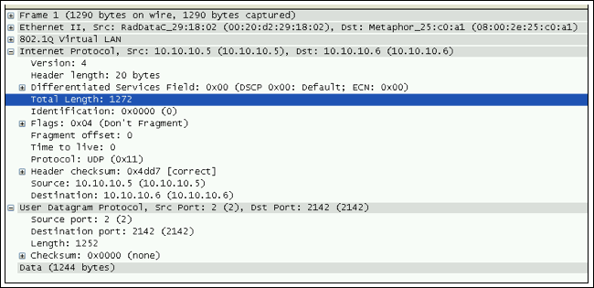
Figure 15. The captured message has different message length information
Figure 15 shows the content of messages with different message length information, number 1.
The user must consider the following lengths: A. Data bytes: message 1 shown in Figure 15 has a total of 1244 bytes. In the binding configuration, we use IP / UDP / CESoPSN protocol. The transmitted E1 TDM data uses 31 time slots, each time slot has 40 frame bytes, then the total TDM data frame byte is 40 × 31 = 1240 frame bytes. After adding 4 bytes of control word, it becomes 1244 bytes. One of the many advantages of using Maxim's TDMoP chip is that in adaptive clock recovery mode, the RTP (real-time protocol) header is not used in the default mode packets, so it can save some bandwidth for payload data. Most other manufacturers use 12-byte RTP. If we use RTP in the TDMoP data bytes, the total data bytes will be 1256 (1244 + 12). After getting the total number of TDM data bytes, in this case 1240 bytes, the user needs to program Maxim's device to also generate 1240 bytes of TDM data, or the number we got in Wireshark.
B. UDP length: Figure 15 shows that the UDP length of message 1 is 1252 bytes, which consists of 1244 bytes of data plus 8 bytes of UDP protocol.
C. IP length: Figure 15 shows that the IP length of message 1 is 1272 bytes, which consists of 1244 bytes of data, 20 bytes of IP header plus 8 bytes of UDP protocol header.
D. Total number of frame bytes: Figure 15 shows that message 1 has a total of 1290 bytes. It consists of 1244 bytes of data, 20 bytes of IP header, 8 bytes of UDP protocol header, 2 bytes of Ethernet type, 4 bytes of VLAN tag plus 12 bytes of source and destination MAC addresses.
Interoperability requires that all message lengths match. If these lengths are different, the user must use the software menu to configure Maxim's TDMoP device to have the same message length.
Ethernet type Maxim's TDMoP devices mainly use the following Ethernet types as known Ethernet types: IPv4 (0x800) IPv6 (0x86DD) MPLS unicast (0x8847) MPLS multicast (0x8848) ARP (0x806) MEF configured in the Mef_ether_type configuration register Ether type MEF OAM Ether type configured in the Mef_oam_ether_type configuration register Specific Ether type configured in the CPU_dest_ether_type configuration register To achieve the interoperability of Maxim ’s TDMoP devices, the user must determine what kind of ether is used for input messages from other TDMoP devices Types of. This type is located after the VLAN ID header byte. The Ethernet type of the input message shown in Figure 16 is 0x800, which indicates that the message is IPv4.

Figure 16. The Ether type value is 0x800, which means it is IPv4
Once the ether type is determined, the user must configure Maxim's TDMoP device to generate the same ether type. Each Ethernet type can be selected by changing the PSN type in the Bundle Configuration menu. The part of the Bundle Configuration menu is shown below.
Main Menu> Bundle Configuration> CES Bundle Configuration ... (P) 11. VLAN ID 1 [1-4095] ... (100) 12. VLAN Priority [0-7] ... (7) 13. IP Tos [0-255] ... (0) 14. IP TTL [0-255] ... (128) 15. PSN Type> (IP) Option 15 in the above menu has the following content: Main Menu> Bundle Configuration > CES Bundle Configuration> PSN Type () 1. IP 2. MPLS 3. L2TPV3 4. Ethernet By selecting the appropriate combination in the Bundle Configuration menu, you can match the Ethernet type of the captured packet.
Summary Interoperability means that different devices and organizations can work together (interoperate). Devices that can interoperate with other products either follow open interface standards or allow configuration changes to directly convert the interface of one product to the interface of another product. By understanding the types of messages generated by other TDMoP devices, Maxim's devices can easily match the message configuration of other TDMoP devices.
If you have further questions about the use of TDMoP products or Maxim ’s telecommunications products, please email var name = "telecom.support @"; var domain = "maxim-ic.com"; document.write ("" + name + domain + ""); telecom. (English only) or Denki (U.S.) contact the Telecommunication Product Application Support Team
Interoperability requirements Interoperability is the ability of a system to work with systems from other manufacturers with little or no intervention from a system administrator. With interoperability, the system can provide services to other systems or accept services from other systems, so that systems of different manufacturers can work together normally.
This application note describes some of the requirements for Maxim's TDM-over-Packet (TDMoP) devices to work with other manufacturers' TDMoP devices. The Maxim TDMoP chips covered in this application note include: DS34T101, DS34T102, DS34T104, DS34T108, DS34S101, DS34S102, DS34S104, and DS34S108.
The message data generated by Maxim's TDMoP device may use different header information than the message data generated by TDMoP devices of other manufacturers. In order to achieve the interoperability of Maxim devices, users need to know the type of settings. The setting type can be one of the following options: IP / UDP / RTP / SAToP IP / UDP / RTP / CESoPSN MEF / CESoETH-unstructured (eg MEF / SAToP) MEF / CESoETH-structured lock (eg MEF / CESoPSN ) Each setting has a different header. In order to achieve interoperability, the packet header of Maxim's TDMoP device must have the same format as the packet header of TDMoP devices of other manufacturers. Users need to compare the packet headers of Maxim's TDMoP devices with those of other manufacturers' TDMoP devices. If there are format differences, this application note will demonstrate how to use Maxim's user guide to adjust the packet header of the TDMoP device.
The TDM-over-Packet (TDMoP) section will define the functional description of the TDM-over-Packet module.
The TDMoP message format transmits TDM data on a packet-switched network. The TDMoP chip needs to encapsulate the TDM data as described in Figure 1 into an Ethernet message.

Figure 1. TDM-over-Packet encapsulates incoming Ethernet packets
Table 1. Ethernet message structure
| Field | DescripTIon |
| Preamble | A sequence of 56 bits (alternaTIng 1 and 0 values) used for synchronizaTIon; gives components in the network TIme to detect the presence of a signal. |
| Start Frame Delimiter | A sequence of 8 bits (10101011) that indicates the start of the packet. |
| Destination and Source Addresses | The Destination Address field identifies the station or stations that are to receive the packet. The Source Address identifies the station that originated the packet. A Destination Address may specify either an individual address destined for a single station, or a multicast address destined for a group of stations. A Destination Address of all 1 bits refers to all stations on the LAN and is called a broadcast address. |
| Type | Ether type |
| Data and Padding | This field contains the data transferred from the source station to the destination station or stations. The maximum size of this field is 1500 bytes. If the size of this field is less than 46 bytes, then padding is used to bring the packet size up to the minimum length. A minimum Ethernet packet size is 64 bytes from the Destination Address field through the Frame Check Sequence. |
| Frame Check Sequence | This field contains a 4-byte cyclical redundancy check (CRC) value used for error checking. When a source station assembles a packet, it performs a CRC calculation on all the bits in the packet from the Destination Address through the Pad fields (that is , all fields except the Preamble, Start Frame Delimiter, and Frame Check Sequence). The source station stores the value in this field and transmits it as part of the packet. When the destination station receives the packet, it performs an identical check. If the calculated value does not match the value in this field, the destination station assumes an error has occurred during transmission and discards the packet. |
VLAN tagging is as specified in the IEEE® 802.1q standard. Packets tagged with 12-bit VLAN identifiers can construct up to 4096 different VLANs. For those applications where the number is insufficient due to this limitation, VLAN nesting implements a two-layer VLAN tag structure, which expands the ID space of VLANs to 16 million VLANs. Each packet can be sent without a VLAN tag, with one VLAN tag or with two VLAN tags (VLAN nesting). Figures 2 and 3 show a VLAN tag and nested VLAN tag respectively.

Figure 2. Single VLAN tag

Figure 3. Nested VLAN tags
The VLAN Tag Protocol ID (TPID) is used to identify the VLAN tag. It can be 0x8100 or the value in the vlan_2nd_tag_identifier configuration register. The user priority field is used to specify a priority level for Ethernet packets. The CFI (Specific Format Indicator) field indicates that there is a routing information field. The VLAN ID field uniquely identifies which VLAN the Ethernet packet belongs to. The following figure shows the headers of different protocols. . Figure 4 shows the UDP / IPv4 header structure. Figure 5 shows the UDP / IPv6 header structure. Figure 6 shows the MPLS header structure. Figure 7 shows the MEF header structure. Figure 8 shows the L2TPv3 / IPv4 header structure. Structure Figure 9 shows the header structure of L2TPv3 / IPv6. Figure 10 shows the header structure of Control Word. Figure 11 shows the header structure of RTP. The following table describes the different fields of the header structure. Table 2 describes the different fields of the IPv4 header structure Table 3 describes the different fields of the UDP header structure Table 4 describes the different fields of the IPv6 header structure Table 5 describes the different fields of the MPLS header structure Table 6 describes the different fields of the MEF header structure Table 7 describes the different fields of the L2TPv3 / IPv4 header structure Table 8 describes the different fields of the L2TPv3 header structure Table 9 describes the different fields of the L2TPv3 / IPv6 header structure Table 10 describes the different fields of the control word header structure Table 11 describes the RTP Different fields of the header structure UDP / IPv4 header

Figure 4. UDP / IPv4 header
Table 2. IPv4 header structure
| Field | Description |
| IPVER | IP version number; for IPv4 IPVER = 4 |
| IHL | Length in 32-bit words of the IP header, IHL = 5 |
| IP TOS | IP type of service |
| Total Length | Length in octets of IP header and data |
| Identification | IP fragmentation identification |
| Flags | IP control flags; must be set to 010 to avoid fragmentation |
| Fragment Offset | Indicates where in the datagram the fragment belongs; not used for TDM-over-packet |
| Time to Live | IP Time-to-Live field; datagrams with zero in this field are to be discarded |
| Protocol | Must be set to 0x11 to signify UDP |
| IP Header Checksum | Checksum for the IP header |
| Source IP Address | IP address of the source |
| Destination IP Address | IP address of the destination |
Table 3. UDP header structure
| Field | Description |
| Source Port Number, Destination Port Number | Either the Source or the Destination Port Number holds the bundle identifier. The unused field can be set to 0x85E (2142), which is the user port number assigned to TDM-over-packet by the Internet Assigned Numbers Authority (IANA). For UDP / IP-specific OAM packets, the bundle identifier is all ones. |
| UDP Length | Length in octets of UDP header and data |
| UDP Checksum | Checksum of UDP / IP header and data; if not computed, it must be set to zero |
UDP / IPv6 header

Figure 5. UDP / IPv6 header
Table 4. UDP header structure
| Field | Description |
| IPVER | IP version number; for IPv6 IPVER = 6 |
| Traffic Class | An 8-bit field similar to the type-of-service (ToS) field in IPv4 |
| Flow Label | The 20-bit Flow Label field can be used to tag packets of a specific flow to differentiate the packets at the network layer. |
| Payload Length | Similar to the Total Length field in IPv4, this field indicates the total length of the IP header and data in octets. |
| Next Header | Similar to the Protocol field in IPv4, this field determines the type of information following the basic IPv6 header. It must be set to 0x11 to signify UDP. |
| Hop Limit | Similar to the Time-to-Live field in IPv4 |
| Source IP Address | Similar to the Source Address field in IPv4, except that this field contains a 128-bit source address for IPv6 instead of a 32-bit source address for IPv4. |
| Destination Address | Similar to the Destination Address field in IPv4, except that this field contains a 128-bit destination address for IPv6 instead of a 32-bit destination address for IPv4. |
MPLS header

Figure 6. MPLS header
Table 5. MPLS header structure
| Field | Description |
| Outer Labels | These MPLS labels identify the MPLS LSP used to tunnel the TDMoMPLS packets through the MPLS network. They are also known as tunnel labels or transport labels. The label number can be assigned either manually or via the MPLS control protocol. There can be zero, one , or two outer labels. |
| EXP | Experimental field |
| S | Stacking bit: 1 indicates stack bottom; S = 0 for all outer labels |
| TTL | MPLS time to live |
| Inner Label | The MPLS Inner Label (also known as the PW label or the interworking label) contains the bundle identifier used to multiplex multiple bundles within the same tunnel. It is always at the bottom of the MPLS label stack, and hence its stacking bit is set. |
MEF header

Figure 7. MEF header
Table 6. MEF header structure
| Field | Description |
| ECID | The Emulated Circuit Identifier (ECID) contains the bundle identifier. |
L2TPv3 / IPv4 header

Figure 8. L2TPv3 / IPv4 header
Table 7. L2TPv3 / IPv4 header structure
| Field | Description |
| IPVER | IP version number; eg, for IPv4 IPVER = 4 |
| IHL | Length in 32-bit words of the IP header, IHL = 5 |
| IP TOS | IP type of service |
| Total Length | Length in octets of header and data |
| Identification | IP fragmentation identification |
| Flags | IP control flags; must be set to 010 to avoid fragmentation |
| Fragment Offset | Indicates where in the datagram the fragment belongs; not used for TDM-over-packet |
| Time to Live | IP Time-to-Live field; datagrams with zero in this field are to be discarded |
| Protocol | Must be set to 0x73 to signify L2TPv3 |
| IP Header Checksum | Checksum for the IP header |
| Source IP Address | IP address of the source |
| Destination IP Address | IP address of the destination |
Table 8. L2TPv3 header structure
| Field | Description |
| Session ID (32 Bits) | Locally significant L2TP session identifier, also contains the bundle identifier; all bundle identifiers are available for use except 0, which is reserved |
| Cookie (32 or 64 Bits) | Optional field that contains a randomly selected value used to validate association of the packet with the expected bundle identifier |
L2TPv3 / IPv6 header

Figure 9. L2TPv3 / IPv6 header
Table 9. L2TPv3 / IPv6 header structure
| Field | Description |
| IPVER | See Table 4 |
| Traffic Class | |
| Flow Label | |
| Payload Length | |
| Next Header | Must be set to 0x73 to signify L2TPv3 |
| Hop Limit | See Table 4 |
| Source Address | |
| Destination Address |
See Table 8 for L2TPv3 header structure.
Control word

Figure 10. Control word
Table 10. Control word structure
| Field | Description |
| RES | Reserved bits—must be set to zero |
| L | Local loss-of-sync (LOS) failure. This bit is set by the CPU. A set L bit indicates that the source has detected, or has been informed of, a TDM physical layer fault that impacts the data to be transmitted. This bit can be used to indicate physical layer LOS that should trigger AIS generation at the far end. Once set, if the TDM fault is rectified, the L bit must be cleared. |
| R | Remote receive failure. This bit is set by the CPU. A set R bit indicates that the source is not receiving packets at the Ethernet port (ie, there is a failure in the direction of the bidirectional connection). This indication can be used to signal congestion or other network-related faults. A remote failure indication may trigger fallback mechanisms for congestion avoidance. The R bit must be set after a preconfigured number of consecutive packets are not received, and must be cleared once packets are received again. |
| M | Defect modifier failure. These bits are set by the CPU. This field is optional. When used, it supplements the L-bit meaning. |
| FRG | Fragmentation field. This field is used for fragmenting multiframe structures into multiple packets in case of CESoPSN structured with CAS bundles. The field is used as follows: 00-Indicates that the entire (unfragmented) multiframe structure is carried in a single packet 01-Indicates the packet carrying the first fragment 10-Indicates the packet carrying the last fragment 11-Indicates a packet carrying an intermediate fragment |
| Length | Includes control word, payload, and RTP header (if it exists), unless it is a UDP / IP packet. It is used when this sum is less than 64 bytes. Otherwise, set to zero. |
| Sequence Number | TDM-over-packet sequence number. This value is defined separately for each bundle and incremented by one for each TDMoP packet sent for that bundle. The initial value of the sequence number is random (unpredictable) for security purposes, and the value is incremented in wrap-around manner separately for each bundle. It is used by the receiver to detect packet loss and restore packet sequence. The HDLC payload type machine supports three different modes for this field: always zero, incremented in wrap-around manner, or incremented in wrap-around value, but skips zero value. For OAM packets (see TDM-over-packet payload), it uniquely identifies the message. Its value is unrelated to the sequence number of the TDMoP data packets for the bundle in question. It is incremented in query messages, and replicated without change in replies. |
RTP header

Figure 11. RTP header
Table 11. RTP header structure
| Field | Description |
| V | RTP version—must be set to 2 |
| P | Padding bit—must be set to 0 |
| X | Extension bit—must be set to 0 |
| CC | CSRC count—must be set to 0 |
| M | Marker bit—must be set to 0 |
| PT | Payload Type. One PT value MUST be allocated from the range of dynamic values ​​for each direction of the bundle. The same PT value MAY be reused for both directions of the bundle, and also reused between different bundles. |
| SN | The sequence number, identical to the sequence number in the control word |
| TS | Timestamp. The RTP header can be used in conjunction with the following modes of timestamp generation: Absolute mode: the chip sets timestamps using the clock recovered from the incoming TDM circuit. As a consequence, the timestamps are closely correlated with the sequence numbers. The timestamp is incremented by one every 125µs. Differential (common-clock) mode: The two chips at bundle edges have access to the same high-quality clock source, and this clock source is used for timestamp generation. |
| SSRC | Identifies the synchronization source. This identifier should be chosen randomly, with the intent that no two synchronization sources within the same RTP session will have the same SSRC identifier. |
How to get the packet content of TDMoP devices from other manufacturers There are some softwares that can be used to analyze the Ethernet packet header. This application note uses Wireshark® software. Users can download this free software from. For more information about Wireshark, please see the Wireshark FAQ (English only).
In order to confirm that the user has correctly sent the message with the correct protocol, the user needs to ensure that the two TDMoP system boards from other manufacturers are synchronized with each other. After completing this step, the user needs to use the Wireshark program to capture the message. Figure 12 shows a screenshot of this program.

More detailed pictures (PDF)
Figure 12. Screen capture of the Wireshark program used to analyze the Ethernet packet header
In order to enable intercommunication between systems, the following requirements must be considered: source port number and destination port number message bytes, IP length, UDP length and total length of data bytes Ethernet type source port number and destination port number message classification module Use TDMoP port number to identify UDP / IP of TDM-over-Packet. TDMoIP_Port_Number can be configured to two different values. Although Maxim's TDMoP device has two TDMoIP_Port_Number registers, in many cases, both registers should be configured to the default value (0x085E) assigned by IANA for TDM-over-Packet. The source port number or destination port number contains the binding identification number. The unused field can be set to 0x85E (2142 decimal), which is the user port number assigned by IANA for TDM-over-Packet. As shown in Figure 4, Maxim's device first inserts the source port number, and then inserts the TDMoP destination port number. Figure 13 shows the contents of the User Datagram Protocol (UDP). The source port number is set to 2 and the TDMoP destination port number is set to 0x85E (2142 decimal).

Figure 13. UDP source and destination port numbers
Some manufacturers insert 0x85E as the source port number of UDP and the destination port number of UDP. In this case, the user must configure the system through the preconfiguration menu. The default values ​​of the Maxim software are as follows:
PreConfig Configuration 1. Link Type E1 2. Bundle Number ID Location Port in DST, Bundle in SRC UDP Port 3. UDP Mask 1FFF 4. VCCV OAM Mask [0-4] 0 5. VCCV OAM Value 1FFF 6. MEF Ethernet Type 88D8 7. MEF OAM Type 0 8. TDMoIP Port Number 1 85E 9. Oscillator Type OCXO (Stratum 3E) 10. RTP Clock Source ABSOLUTE 11. Common clock Rate 19440000 12. IP Version IPv4 13. Clock Recovery Smart Statistics Enable 14. One or The second item of the Two Clock Mode One Maxim software menu is used to select the desired Bundle Number ID Location. The second item of the above menu provides the following options:
Bundle Number ID Location 1: Ignore port, Bundle in SRC UDP PORT, 2: Port in DST, Bundle in SRC UDP PORT 3: Port in SRC, Bundle in DST UDP PORT, 4: Ignore Port, Bundle in DST UDP PORT on top In the menu, the default Bundle Number ID Location of the Maxim device is option 2: “Port in DST, Bundle in SRC UDP PORTâ€. In order to make Maxim's equipment interoperable with other manufacturers' equipment, users need to choose option 1, 3 or 4 appropriately. For example, a TDMoP manufacturer's device inserts the Destination port at the Source (SRS) position, and inserts the bound port number at the Destination (DST). If the user selects option 3 in the above menu, the UDP source port Bundle Number ID Location is set to 0x85E (2142 decimal), and the UDP destination port will be 2, as shown in Figure 14. In this way, the TDMoP header of that manufacturer can be matched, so they can interoperate.

Figure 14. UDP source and destination port numbers are reversed from Figure 13
Packet bytes, IP length, UDP length and total length of data bytes

Figure 15. The captured message has different message length information
Figure 15 shows the content of messages with different message length information, number 1.
The user must consider the following lengths: A. Data bytes: message 1 shown in Figure 15 has a total of 1244 bytes. In the binding configuration, we use IP / UDP / CESoPSN protocol. The transmitted E1 TDM data uses 31 time slots, each time slot has 40 frame bytes, then the total TDM data frame byte is 40 × 31 = 1240 frame bytes. After adding 4 bytes of control word, it becomes 1244 bytes. One of the many advantages of using Maxim's TDMoP chip is that in adaptive clock recovery mode, the RTP (real-time protocol) header is not used in the default mode packets, so it can save some bandwidth for payload data. Most other manufacturers use 12-byte RTP. If we use RTP in the TDMoP data bytes, the total data bytes will be 1256 (1244 + 12). After getting the total number of TDM data bytes, in this case 1240 bytes, the user needs to program Maxim's device to also generate 1240 bytes of TDM data, or the number we got in Wireshark.
B. UDP length: Figure 15 shows that the UDP length of message 1 is 1252 bytes, which consists of 1244 bytes of data plus 8 bytes of UDP protocol.
C. IP length: Figure 15 shows that the IP length of message 1 is 1272 bytes, which consists of 1244 bytes of data, 20 bytes of IP header plus 8 bytes of UDP protocol header.
D. Total number of frame bytes: Figure 15 shows that message 1 has a total of 1290 bytes. It consists of 1244 bytes of data, 20 bytes of IP header, 8 bytes of UDP protocol header, 2 bytes of Ethernet type, 4 bytes of VLAN tag plus 12 bytes of source and destination MAC addresses.
Interoperability requires that all message lengths match. If these lengths are different, the user must use the software menu to configure Maxim's TDMoP device to have the same message length.
Ethernet type Maxim's TDMoP devices mainly use the following Ethernet types as known Ethernet types: IPv4 (0x800) IPv6 (0x86DD) MPLS unicast (0x8847) MPLS multicast (0x8848) ARP (0x806) MEF configured in the Mef_ether_type configuration register Ether type MEF OAM Ether type configured in the Mef_oam_ether_type configuration register Specific Ether type configured in the CPU_dest_ether_type configuration register To achieve the interoperability of Maxim ’s TDMoP devices, the user must determine what kind of ether is used for input messages from other TDMoP devices Types of. This type is located after the VLAN ID header byte. The Ethernet type of the input message shown in Figure 16 is 0x800, which indicates that the message is IPv4.

Figure 16. The Ether type value is 0x800, which means it is IPv4
Once the ether type is determined, the user must configure Maxim's TDMoP device to generate the same ether type. Each Ethernet type can be selected by changing the PSN type in the Bundle Configuration menu. The part of the Bundle Configuration menu is shown below.
Main Menu> Bundle Configuration> CES Bundle Configuration ... (P) 11. VLAN ID 1 [1-4095] ... (100) 12. VLAN Priority [0-7] ... (7) 13. IP Tos [0-255] ... (0) 14. IP TTL [0-255] ... (128) 15. PSN Type> (IP) Option 15 in the above menu has the following content: Main Menu> Bundle Configuration > CES Bundle Configuration> PSN Type () 1. IP 2. MPLS 3. L2TPV3 4. Ethernet By selecting the appropriate combination in the Bundle Configuration menu, you can match the Ethernet type of the captured packet.
Summary Interoperability means that different devices and organizations can work together (interoperate). Devices that can interoperate with other products either follow open interface standards or allow configuration changes to directly convert the interface of one product to the interface of another product. By understanding the types of messages generated by other TDMoP devices, Maxim's devices can easily match the message configuration of other TDMoP devices.
If you have further questions about the use of TDMoP products or Maxim ’s telecommunications products, please email var name = "telecom.support @"; var domain = "maxim-ic.com"; document.write ("" + name + domain + ""); telecom. (English only) or Denki (U.S.) contact the Telecommunication Product Application Support Team
IEEE is a registered service mark of the American Institute of Electrical and Electronics Engineers.
Wireshark is a registered trademark of Gerald Combs.
Cixi Xinke Electronic Technology Co., Ltd. , https://www.cxxinke.com