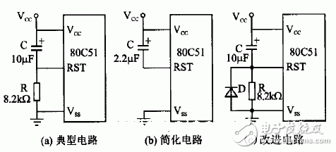
The following delay reset circuits are formed by using the charging time of an external RC branch on the RST pin of the microcontroller. A typical reset circuit is shown in Figure (a), where the RC values ​​are provided in the original manual. Figure (b) is a simplified reset circuit, and Figure (c) adds a diode D to Figure (a) to facilitate the rapid discharge of capacitor C, in preparation for the next power-on reset delay. After a series of delays, the microcontroller begins to enter the normal program running state according to the operating frequency of the clock source.

Multi-Function Electric Blender
Multi-Function Electric Blender,High Speed Blender,Heating Cooking Blender,Cooking Blender For Home
Shandong Sangle Group Co.,Ltd. , https://www.sangle-group.com