Part 1: Design Overview
This article refers to the address: http://
Safety Driving Assist (SDA) is an important part of the current international intelligent transportation system research. It mainly solves the problem of traffic safety and relieves the two problems of traffic congestion and environmental pollution that plague the transportation field. Based on this, many countries in the world are strengthening research in the field of vehicle safety assisted driving technology. Research on safety-assisted driving technology focuses on lane departure warning, front obstacle detection, and driver status monitoring. In the past 20 years, the lane departure warning system has been receiving more and more attention as an integral part of the field of safety-assisted driving research. Many countries have invested a lot of manpower, material resources and financial resources for system research and development.
Research background of lane departure warning system:
The Lane Departure Warning System (LDWS) refers to the use of an alarm to alert the driver when the vehicle deviates from the normal lane when the driver does not indicate the lane change of the vehicle during high-speed driving. A car active safety device that corrects the direction of the vehicle. The lane departure warning system will be another safety device installed in the car after the seat belt and airbag. In the United States, casualties caused by lane departures accounted for 37.0% of all vehicle casualties in 1994, 42.0% in 2000, and 43.0% in 2001, an average annual increase of 0.75 percentage points. The lane departure warning system can send a warning signal to the driver when the vehicle deviates from the lane line, prompting the driver to correct the direction of the vehicle and alert the driver to concentrate. Studies have shown that lane departure warning systems can reduce lane departures by at least 24%. Some countries in the world have successfully developed a number of distinctive lane departure warning systems, such as Auto Vue system, AWSTM system, DSS system, SCARF system and ALVINN system. In China, the research on lane departure warning started late, and no related products have been released. Only the State Key Laboratory of Vehicle Dynamic Simulation of Jilin University and the School of Instrument Science and Engineering of Southeast University conducted some exploratory research. Exploratory research shows that the vision-based lane departure warning system is a practical solution.
MicroBlaze embedded soft core is a RISC processor soft core that can be embedded in FPGA by Xilinx. It has the advantages of fast operation, low resource consumption and strong configurability. It is widely used in communication, military and high-end consumption. Market and other fields. Xilinx's MicroBlaze 32-bit soft processor core is a collection of standard peripherals that support the CoreConnect bus. Operating at 150MHz, the MicroBlaze processor delivers 125 D-MIPS performance, making it ideal for designing complex embedded systems for the networking, telecom, datacom, and consumer markets.
Design summary:
This topic is based on the MicroBlaze microprocessor IP core on the Xilinx FPGA development board. Together with other peripherals, it designed a car departure warning system for drivers driving on highways or urban roads. The system consists of an image acquisition subsystem, an FPGA development board, and other devices. The image acquisition subsystem can collect real-time data on the road surface. After the data enters the system, it is transformed into a processable format in real time. Within the processor, the pre-processing is first performed to filter out the noise mixed during image capture, and then the vehicle is detected. Relative to the position of the road marking line. The input information stream of the road image is transformed into a series of lines that outline the surface of the road. Look for the edge in the data field to find the lane markings. These edges actually form the boundary where the vehicle should travel forward. The processor must keep track of these marking lines to determine if the driving route is normal. Once the vehicle is found to inadvertently deviate from the roadway, the processor outputs a signal to drive the alarm circuit to make the driver correct the driving route immediately. The alarm circuit uses a buzzer to emit a warning sound.
Part II: Design Structure
1. System block diagram introduction
No matter which kind of lane departure warning system can be divided into three basic modules: road and vehicle state perception module, lane departure evaluation algorithm module and signal alarm circuit, the basic process of system operation shown in Figure 1 is: state perception The module senses the road geometry and the dynamic parameters of the vehicle. Then the lane departure evaluation algorithm evaluates the possibility of lane departure. Once the vehicle is found to inadvertently deviate from the roadway, the processor outputs a signal to drive the alarm circuit to make driving. The crew immediately corrected the driving route. The alarm can be in the form of a buzzer or a horn, or a language prompt, or a vibrating seat to alert the driver.

Figure 1 system design block diagram
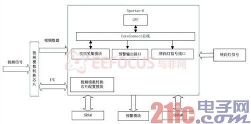
The lane departure warning system is specifically for hardware. The video image is sampled by a camera mounted on the vehicle, and then the video image represented as an analog signal is digitally converted, and the digital video information is transmitted to the processor unit. According to the algorithm requirements, the real-time state of the vehicle deviating from the lane is obtained. If there is a lane departure or a lane departure will occur, the system will alert the driver through the alarm circuit to prevent accidents.
2. Hardware block diagram

Figure 2 hardware block diagram
3. Software flow chart
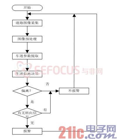
Software flow chart shown in Figure 3.

Figure 3 software flow chart
1. Road image acquisition
This paper mainly studies the application of lane detection technology in lane departure warning. In the process of image acquisition, camera intensity caused by illumination intensity, obstacle obstruction, roadside trees and uneven road surface will affect the lane line information in the image. Therefore, in order to accurately extract the lane line parameters, it is necessary to preprocess the acquired road image before the lane line detection. In the image processing algorithm, no algorithm can be applied to various types of images, and each algorithm has its own limitations. Therefore, in practical applications, a large number of experiments are needed, and combined with the needs of the lane departure warning system, an algorithm suitable for the system is selected. The road surface suitable for the detection algorithm of this paper is a highway and urban road that may have at least two lanes separated by lane lines in the sky or mountain background above the field of view of the camera.
2. Image preprocessing
According to the projection theory, when the optical axis of the camera is parallel to the ground plane, and the vehicle is generally in the ground part below, the area with the vehicle in the lower part of the image is our region of interest, and only needs to analyze this part. In the preprocessing, the lower half of the image is generally divided into the parts of interest, and the upper part is uniformly processed in black, so that the information represented by the white portion after the preprocessing is the lane line. This is better in line with the actual situation, and the algorithm is simple, avoiding the redundancy of processing a large amount of information, and improving the calculation rate. The pretreatment is completed in four steps:
a. Grayscale. The reason why the graying is done here is because the stone asphalt pavement is dark black, and the yellow line is light color. After graying, the two appear black and white on the image, which is easy to operate and easy for later processing. .
b. Use spatial filtering techniques to remove unwanted noise from the image. Available algorithms are histogram equalization, domain averaging, median filtering, and so on.
c. Segmentation of the image using binarized segmentation of the road image to obtain significant lane line features, greatly simplifying the complexity of later analysis and detection of lane marking lines. Available algorithms include histogram waveform analysis, maximum entropy method, and maximum class variance method.
d. Divide the area of ​​interest. Reduce the redundant data by reducing the range of the detection area, and increase the calculation speed. Common partitioning algorithms for regions of interest are: based on grayscale projection methods, dynamic regions of interest.
3. Design and implementation of lane detection algorithm
The fast and accurate identification of the lane line is the premise and basis for real-time and robustness of the lane departure warning system. Based on the principle of lane line detection based on curve fitting, this paper proposes a best choice based on LMedsquare. set. The core idea of ​​LMedsquare is to repeat the random selection of data subsets until at least one subset of the data can achieve a certain degree of confidence (such as 95%), which is a random sampling algorithm. The lane line detection algorithm consists of the following steps:
a. Selection of seed points. To get the lane line coordinate equation accurately, you need to find the center point of the lane line first, and then fit the lane line to the set of lane center points. Therefore, you need to find the center point of the lane line. Here, the center line of the lane line can be found according to the characteristics of the lane line after binarization of the lane line image, and preparation for the next lane line parameter fitting is performed.
b. Detection of lane markings. After the seed points are classified, we need to judge whether the number of seed points to be fitted is sufficient. When the road conditions are good, the near-field lane lines are relatively clear, and the bottom-up scans are classified, and generally a relatively good number of lanes are obtained. Line seed points, you can directly use LMedsquare to select the best subset of lane line detection algorithm for parameter fitting.
c. Least squares line fit based on the best subset. Fitting the curve by least squares is a commonly used fitting algorithm in intelligent navigation technology, but its biggest disadvantage is that it is sensitive to noise. In other words, solving the noise effect is the premise of accurately fitting the lane line parameters. basis. Therefore, when the number of seed points is sufficient after the lane line seed points are classified, the best subset can be selected by the idea of ​​LMedsquare curve fitting technique to remove excess noise, and then the least square method is used in the best subset. Performing a straight line fit will give you good results.
Part III: System Principles and Technical Features
1. Firstly use the EDK software XPS (Xilinx Platform Studio) to build a MicroBlaze soft core system, the FPGA internal CPU peripheral modules are written in Vhdl language, and then the FPGA external module is connected to the FPGA through the FPGA interface.
2. Road image acquisition can use CCD camera. The CCD camera is mounted on the inside of the windshield, in the center of the bridge, and uses a telephoto lens to collect the road surface. Pavement information stream processing application Philips Semiconductor's video decoding chip SAA7115, which is a multi-channel input video decoder, supports a variety of video signal formats, such as PAL, NTSC, SECAM. The SAA7115 automatically detects and completes the conversion of the input video signal. The SAA7115 offers high performance for capturing a wide range of standard definition signals. The chip is packaged in a small 100-pin QFP14X142100A with integrated anti-aliasing filters and ADLLT (Adaptive Digital Line Length Tracking) and supports multiple video signal formats such as PAL and NTSC. System, SECAM system, etc., can automatically detect and complete the conversion of the input video signal. Based on the above characteristics, this design uses it as a video coding chip to achieve seamless connection with the FPGA. Because the processing speed of the peripheral circuit and the FPGA is very different, the signal stream is first buffered by the SN74CBT3245 chip, and then sent to the processor for the lane feature to be extracted.
3. Image preprocessing technology
The image contains a wealth of information, and in lane recognition, not all information is needed. Therefore, it is necessary to process the collected continuous images, remove unnecessary information, and enhance useful information, which is beneficial for subsequent processing. When performing image pre-processing, the lane detection section feeds back it, which can increase its processing speed. Specific steps include image grayscale transformation, image noise filtering, image edge detection, and image binary segmentation.
During the acquisition process, due to the influence factors such as illumination intensity and obstacle occlusion, the lane line information in the captured image is affected. Therefore, in order to accurately extract the lane line parameters, it is necessary to pre-process the acquired road image before the lane line detection. In the image processing algorithm, no algorithm can be applied to various types of images, and each algorithm has its own limitations. Therefore, in practice, a large number of experiments are needed, and combined with the needs of the lane departure warning system, an algorithm suitable for the system is selected.
Spatial filtering is first used to remove unwanted noise from the image.
The binarization of the road image is then performed to segment the image, which will compress the data in large quantities and will simplify subsequent analysis and processing.
Then, the division of the lane line feature point search area and the division of the region of interest are performed, and the redundant data is reduced by reducing the detection area range, thereby improving the operation speed.
4. Lane line recognition algorithm
The first is the lane line recognition technology based on Hough transform. First extract the lane line sample points and then perform a Hough fit on the sample points. The advantage of using this method for lane line detection is that it is not affected by the discontinuity of the lane line and has good anti-interference. However, it also has shortcomings, and it needs to be verified and improved by actual experimentation.
The second is based on LMedsquare to select the best subset combined with Kalman prediction lane line detection algorithm. First, the seed point is selected, then the lane identification line is detected, and finally the least square line fitting based on the best subset is performed.
5. Lane departure decision
We rely on the machine vision early warning decision method, we can use the image-based lane line angle method to deviate from the early warning decision method. There are two kinds of alarm methods: one is to set an angle threshold value for the large yaw angle boundary, if several consecutive frames The test result shows that the vehicle position is in a large yaw angle state, and an alarm is immediately issued. The second is to set an angle domain value as the boundary of the small yaw angle. When the vehicle position is in the small yaw angle state, it waits for the continuous multi-frame image processing result. If the continuous multi-frame image shows that the vehicle yaw angle is continuously increasing, Then immediately alarm.
6. Extended function:
When the person actively changes the lane, the indication signal is turned on before leaving the road, and the alarm system does not alarm when the vehicle deviates from the lane.
Technical features:
1. Using the EDK software XPS to build the MicroBlaze soft core system, the CPU design requirements of the system design are realized simply and efficiently. The various interface modules in the FPGA will be written in the vhdl language.
2. There are many details of image processing, and the algorithm of each step of image processing is diverse. In practical application, the hardware used should be combined. After the actual experiment, the most suitable algorithm should be selected in combination with the system.
3. Select the part of interest in the image preprocessing algorithm. It not only improves the calculation rate, but also reduces unnecessary information interference, which lays a good foundation for improving the accuracy and timeliness of detection.
The lane-line detection algorithm adopts the least squares fitting method based on the best subset after selecting the seed point, which can well remove the noise interference problem often encountered in the least squares straight line fitting method.
5. The camera has an automatic correction function. When sitting in a car, the chassis of the car will sink and tilt, and the camera will automatically correct and still detect the off-road information.
Integrity and caring is the purpose of our service. Affordable, cost-effective, carefully selected materials, quality Seiko. On-demand customization, fast delivery, considerate service, honest cooperation. We have used oil in many physical factories, the manufacturers directly connect with customers, and have many years of industry experience. More high-quality materials to create high-quality products.
We specialize in the production of terminal blocks, there are different types, PCB Terminal Block and Din Rail Terminal Block. You can go to our website to browse. More Spring Terminal is on sale, which can be customized according to your needs. If you are interested, you can consult us. If you need some Terminal Pins or other Terminal Block Accessories, you can also consult us, we support customization and wholesale.

module terminal block,terminal block module,terminal block breakout module
Sichuan Xinlian electronic science and technology Company , https://www.sztmlchs.com