In the motor control system, the client needs to set the operating parameters of the motor through the host computer, and the controlled motor also transmits various operating status information to the remote control terminal in real time. The serial communication has low connection and low cost. Simple and reliable, it is widely used. In this paper, the SCI serial communication interface is used to realize the communication connection between the DSP controller and the PC. The motor control system must also have a digital display drive circuit to facilitate the on-site control personnel to know the current motor speed and other information in time, so use SPI synchronous serialization. It is necessary to implement communication between DSP and peripheral devices. The serial peripheral interface SPI of the digital signal processing chip TMS320LF2407A DSP and the serial communication interface SCI module are analyzed. In the motor control experiment system, an example of serial communication application composed of these two modules is given. The focus is on the high hardware design of the relevant serial communication interface circuit.
Hardware circuit design of serial communication interface module
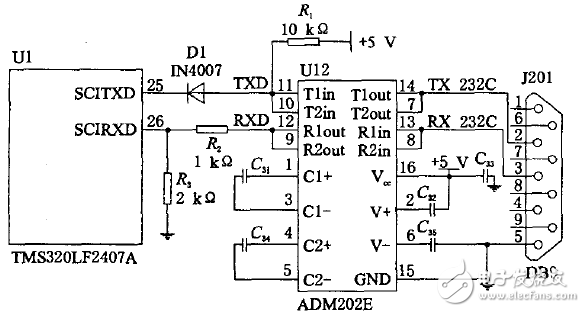
The operating parameters of the motor, such as steering, speed and position signals, are determined by the host and transmitted to the DSP via RS232 serial communication. The DSP then returns the running result to the motor control system of the host to realize the remote client and the controlled motor. Communication between. Since the host computer (PC) generally has an RS232 interface, we use the serial port of the host computer and the asynchronous serial port SCI of the lower computer DSP to perform RS232C communication and data exchange, so as to realize the detection of the controlled object on the industrial site by the computer. And control. The serial communication interface circuit of TMS32OLF24O7A is shown as in Fig. 2. The circuit uses a driver chip ADM2O2E that conforms to the RS232 standard for serial communication. The ADM2O2E chip has low power consumption and high integration. It is powered by +5 V and has two receive and transmit channels. Since the TMS320LF2407A is powered by +3.3 V, a level shifting circuit must be added between the ADM202E and the TMS320LF2407A. This article uses a diode (1N4oo7) and three resistors for level shifting.

Figure 2 serial communication interface circuit
The experimental system realizes the communication connection between the DSP controller and the host computer by using the SCI serial communication interface circuit of the DSP, and the whole interface circuit is simple and highly reliable. The DSP controller uploads the real-time running status of the control system to the upper computer for storage and analysis through the SCI serial communication interface circuit, and the upper computer controls the command through the SCI serial communication interface circuit (for example, start, stop, forward, Inversion, running speed, etc.) are sent to the DSP controller for real-time control of the motor control system. The serial communication rate of this test system is variable, and the default baud rate is l 9200, which is adjustable from l200, 2400, 4800, 9 600, to l9 200.

SPI and MAX7219 hardware connection circuit
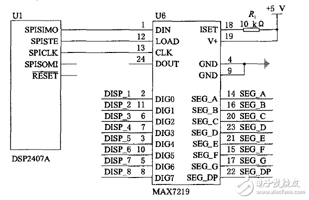
A typical application circuit for the MAX721 9 is shown in the figure, which is an 8-bit LED display driven by a single MAX7219. The DSP is set to operate in master mode by register settings, and the MAX7219 acts as a slave. The 2407A DSP's SPISIMO, SPISTE, and SPICLK are connected to the DIN, CLK, and LOAD terminals of the MAX72l9, respectively. The DISP_l~DISP-8 of the MAX7219 is connected to the 8-bit digital terminal. The SEG-A~SEG-GP is connected to the 7-segment display segment. End and decimal point drive. The SPI provides a serial clock to the entire communication network through the SPICLK pin to control the data transmission of the system. The MAX7219 is provided with a chip select signal through the SPISSTE pin, which is active low; the data is output to the DIN pin of the MAX7219 through the SPISIMO pin. Resistor R changes the brightness of the LED, and the peak drive current per segment is about 100 times the current in R. The value of R cannot be less than 10 kl2. In actual use, you can first adjust the brightness with an adjustable resistor, and then replace it with a fixed resistor of the same resistance. It should be noted here that the MAX7219's segment current normal operating range is l0b40 mA. When the segment current exceeds 40 mA, a current spreading circuit must be added.
Wire Condenser
The condensing unit is used for refrigerator temperature control devices, air conditioners, heat pumps and coolers. They are called [gas refrigerants" by compression in the form of heat, then pumped through the coil system, and heated and cooled by the coiled air. The condenser unit is mainly used in commercial refrigeration systems and industrial refrigeration systems. The condensing unit mainly consists of Mono-Blocks For Cold Storage,Semi Hermetic Condensing Unit,Box Type Condensing Unit ,we can follow the customer's requirements to produce the correct size of the condensing unit.
Wire Condenser,Cold Room Condenser,Evaporator Condenser,Refrigerator Condenser
FOSHAN SHUNDE JUNSHENG ELECTRICAL APPLIANCES CO.,LTD. , https://www.junshengcondenser.com