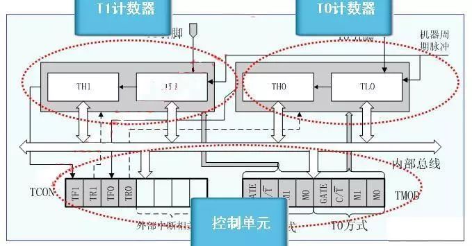
Timer/counter structure
The essence of the timer/counter is to add 1 counter (16 bits), which consists of two registers, the upper 8 bits and the lower 8 bits. TMOD is the working mode register of the timer/counter to determine the working mode and function; TCON is the control register, which controls the start and stop of T0 and T1 and sets the overflow flag.
How the timer/counter works
Count pulse source for counter input
The clock oscillator output pulse of the system is generated after dividing by 12;
External pulse source for T0 or T1 pin input.
Counting process
Each pulse counter is incremented by one. When the counter is all ones (ie, FFFFH), a pulse is input to zero the counter, and the overflow of the counter sets TF0 or TF1 in TCON to issue an interrupt request to the CPU ( When the timer/counter interrupt is enabled). If the timer/counter is operating in the timing mode, it means that the timer time has expired; if it is working in the count mode, it means that the count value is full.
Timing application
Used as a timer: set to timer mode at this time, plus 1 counter is to count the internal machine cycle (1 machine cycle is equal to 12 oscillation cycles, that is, the count frequency is 1/12 of the crystal frequency). The count value N multiplied by the machine period Tcy is the timing time t.
Counting application
Used as counter: Set to counter mode at this time, the external event count pulse is input to the counter by T0 or T1 pin. The counter is incremented by one for each external pulse. However, the microcontroller has a basic requirement for external pulses: the duration of the pulse must be greater than 1 machine cycle.
Working mode register (TMOD)
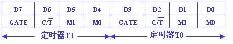
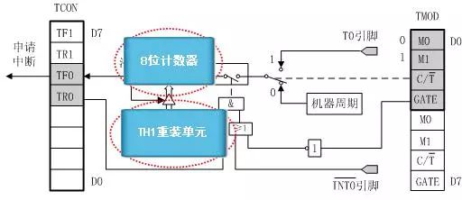
GATE: Gate position.
When GATE=0, as long as the TR0 or TR1 in TCON is set to 1 by software, the timer/counter can be started; (ie, a start condition is required)
When GATE=1, it is necessary to use software to make TR0 or TR1 be 1 and the external interrupt pin is also high to start the timer/counter operation, that is, two start conditions are required.
C/T: Timing/counting mode selection bit.
C/T =0 is the timing mode; C/T =1 is the counting mode.
M1M0: Working mode setting bit.
Counter working mode selection
M1 M0 working mode function description
0 0 mode 0 13-bit counter
0 1 mode 1 16-bit counter
1 0 mode 2 automatic reloading of 8-bit counters
1 1 Mode 3 Timer 0: Divided into two 8-bit
Timer 1: Stop counting
Timer/counter control
Control register TCON
The lower 4 bits of TCON are used to control external interrupts, as described earlier. The upper 4 bits of TCON are used to control the start and interrupt requests of the timer/counter. Its format is as follows:

TF1 (TCON.7): T1 overflow interrupt request flag. The hardware automatically sets TF1 to 1 when the T1 count overflows. TF1 is automatically cleared by hardware after the CPU responds to the interrupt. TR1 (TCON.6): T1 start/stop control bit. 1: Start 0: Stop
TF0 (TCON.5): T0 overflow interrupt request flag, its function is the same as TF1.
TR0 (TCON.4): T0 start/stop control bit. 1: Start 0: Stop
How the timer/counter works
Mode 0
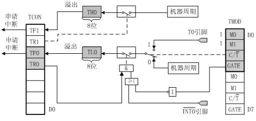
Mode 0 is a 13-bit count, which is composed of the lower 5 bits of TL0 (higher 3 bits unused) and the 8 bits of TH0. The lower 5 bits of TL0 overflow to TH0. When TH0 overflows, the TF0 flag in TCON is set. The CPU issues an interrupt request.
Mode 1
The number of count bits of mode 1 is 16 bits, and TL0 (TL1) is used as the lower 8 bits, and TH0 (TH1) is used as the upper 8 bits, which constitutes a 16-bit plus 1 counter.
Mode 2
Mode 2 is an 8-bit counting method that automatically reloads the initial value.
In mode 2, when the counter reaches 255 (FFH) overflow, the CPU automatically loads the value of TH into the TL without user intervention. It is therefore particularly suitable for use as a more accurate pulse signal generator.
Mode 3
Mode 3 is only applicable to the timer/counter T0. When the timer T1 mode 3 is equivalent to TR1=0, the counting is stopped.
Mode 3 divides T0 into two independent 8-bit counters TL0 and TH0.