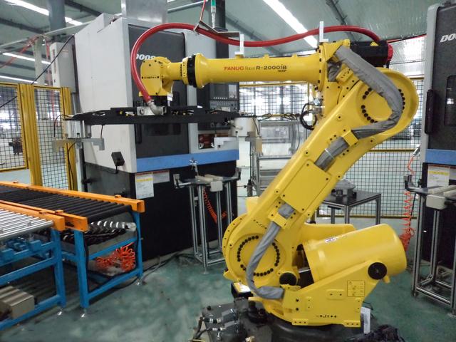
FANUC industrial robot motion position data analysis
The location data stores the position and posture of the robot . When the motion instruction is taught, the position data is simultaneously written to the program.
The position data includes: a joint coordinate value based on the joint coordinate system, and a Cartesian coordinate system coordinate value expressed by a tool position and a posture in the work space. The Cartesian coordinate system coordinate values ​​are used as position data under the standard setting.
The position data based on the coordinates of the Cartesian coordinate system is defined by four elements. The position of the tool cusp (tool coordinate system origin) in the Cartesian coordinate system coordinate system, the inclination of the tool direction (tool coordinate system), the shape, and the Cartesian coordinate system coordinate system used.

Position data (orthogonal coordinate system coordinate values):
UF, UT, (X, Y, Z, w, p, r), Configuraition
UF: User coordinate system number
UT: Tool coordinate system number
"x, y, z": position
"w,p,r": pose
Configuraition: Form
(1) Verify the Cartesian coordinate system
The verification of the Cartesian coordinate system detects the coordinate system in which the coordinate system number is used when reproducing the position data based on the rectangular coordinate values.
When 0 to 10 is specified in the tool coordinate system number, and 1 to 9 is specified in the user coordinate system number, when the coordinate system number specified here is different from the currently selected coordinate system number, in order to ensure safety Alarm without executing the program.
The coordinate system number is written to the position data when the position is taught. To change the coordinate system number to be written, use the tool change/coordinate replacement offset function.
(2) Tool coordinate system number (UT)
Tool coordinate system number, specified by the coordinate system number of the mechanical interface coordinate system or the tool coordinate system. The coordinate system on the tool side is thus determined.
0: Use the mechanical interface coordinate system.
1 to 10: The tool coordinate system using the specified tool coordinate system number.
F: Coordinate system using the currently selected tool coordinate system number.
(3) User coordinate system number (UF)
User coordinate system number, specified by the coordinate system number of the world coordinate system or user coordinate system. The coordinate system of the work space is thus determined. On LRMate, this value is fixed to 0 (zero).
0: Use the world coordinate system.
1 to 9: User coordinate system using the specified user coordinate system number.
F: Coordinate system using the currently selected user coordinate system number.
(4) Position and posture
The position (X, Y, Z) represents the position of the tool cusp (tool coordinate system origin) in the Cartesian coordinate system in three-dimensional coordinate values.
The posture (w, p, r) is expressed by the rotation angle around the X, Y, and Z axes in the Cartesian coordinate system.
(5) Form
Configuration refers to the posture of the main part of the robot. There are a plurality of forms that satisfy the conditions of the Cartesian coordinate system coordinate values ​​(x, y, z, w, p, r). To determine the shape, you need to specify the joint configuration (JointPlacement) and the number of rotations (TurnNumber) for each axis.
Pin Header Connector,Pin Header Female,Male Header Pins,Right Angle Pin Header
Cixi Xinke Electronic Technology Co., Ltd. , https://www.cxxinke.com