Abstract: In fuel cell vehicles, power conversion is a core issue. Combined with the characteristics of the fuel cell, the shortcomings of the existing converters in the fuel cell vehicle are briefly explained. At the same time, in order to overcome the inherent shortcomings of the two-stage structure of the traditional fuel cell vehicle power converter and further improve its stability, a high-performance Z-source inverter is proposed, and the working principle of the structure is analyzed. A novel three-phase voltage space vector modulation method with a straight-through zero vector is introduced. The working characteristics and the generation method of the through-zero vector are introduced, and relevant simulation experiments are carried out. The simulation results show that the circuit structure can achieve high performance requirements and is suitable for application in fuel cell vehicles.
Key words: fuel cell vehicle; power conversion; high-performance Z-source inverter; space vector modulation
0 INTRODUCTION In recent years, with the rapid growth of automobile demand, oil imports have increased significantly, making national energy security a major challenge. At the same time, environmental problems have become increasingly prominent. According to statistics, 60% of urban pollution comes from automobiles. Compared with traditional vehicles, fuel cell vehicles have many advantages such as no pollution, high work efficiency, low noise, stable driving and no dependence on petroleum. They are the future development direction of the automobile and have received extensive attention and support from the society.
In fuel cell vehicle systems, fuel cells and batteries are the source of energy required for the entire vehicle, and the converter is an important part of the energy flow of the entire power system. The converter is a periodic on/off switch control device between the fuel cell and the battery, and has the function of adjusting voltage and converting voltage. For the fuel cell vehicle, the converter in the drive system should include DC/DC (DC- DC) converters and DC/AC (DC-AC) converters.
The power of the fuel cell vehicle wheel comes from the rotation of the motor. At present, the application of the DC motor in the fuel cell vehicle is gradually replaced by the AC motor. At present, the most widely used and most favored asynchronous motor and permanent magnet motor are often controlled. It is done by adding the corresponding three-phase alternating current to it. Therefore, an inverter is required in the fuel cell vehicle to complete the DC/AC conversion. The facts also show that the AC motor drive system is the mainstream of the electric drive system of electric vehicles in the future.
The traditional fuel cell vehicle realizes the wide range and multi-mode speed regulation of the AC motor by the coordination adjustment of the DC/DC converter and the rear stage DC/AC converter. The DC/DC converter controls the maximum output current and power of the fuel cell. To protect the fuel cell while regulating the voltage on the system line; the DC/AC converter acts as a power conversion control, converting the electrical energy on the system bus into electrical energy suitable for the operation of the motor, while controlling the operation of the motor, Form a typical two-stage power change.
The traditional Boost topology is difficult to boost. Because the topology boost factor is large, the switch-on ratio is close to 1, so that the switch on-time is too long and the switch-off time is too short, resulting in excessive loss and temperature rise, which affects practicality. Limit the range of voltage regulation. However, the commonly used inverter device faces the additional Boost boost chopper circuit, which increases the system cost and reduces the conversion efficiency. The inverter will damage the switch tube due to any control failure or electromagnetic interference. In order to avoid the dead zone of the switch tube, the dead zone is added to affect the output current waveform, and there are a lot of harmonics and other problems.
In general, two-stage efficiency is lower than that of a single-stage system. The new Z-source network can realize the buck-boost conversion function by using its unique passive network, and it also maintains a single-stage structure and high efficiency, and has good research value. When the input voltage of the fuel cell is low, the Z source network works in the boost mode through the introduction of the through time; when the input voltage is high, the through time is not required, and the Z source network operates in the buck mode. Therefore, the Z-source inverter network proposed in this paper can adapt well to a wide range of changes in the output voltage of automotive fuel cells. The Z-source capacitor voltage closed-loop control is used to stabilize the capacitor voltage value at a reasonable given value, so that the DC bus voltage and output voltage remain stable.
The traditional Z-source inverter has some shortcomings. This paper introduces a new type of Z-source inverter with higher performance, which makes the Z-source inverter more perfect on the basis of the traditional structure, and is more satisfied with the fuel cell vehicle. Some requirements have high research value and application value. By controlling the voltage space vector modulation method, a straight-through zero vector is applied in the traditional zero vector action interval, and the DC voltage can be controlled simultaneously with respect to the sinusoidal pulse width modulation without affecting the effective output voltage vector. Other methods have obvious advantages. However, the conventional SVPWM method has no through state and cannot be directly applied to the Z source inverter. This paper gives an implementation method for this problem. At the same time, the high-performance new Z-source inverter topology, compared with the traditional Z-source structure, will have one more switch tube on the DC voltage side, so the switch control is also described in the paper.
1 Z source inverter
1.1 Topology and working principle of traditional Z-source inverter The main circuit topology of voltage-type three-phase Z-source inverter is shown in Figure 1.
This article refers to the address: http://
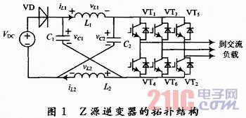
Where: VDC is the DC supply voltage.
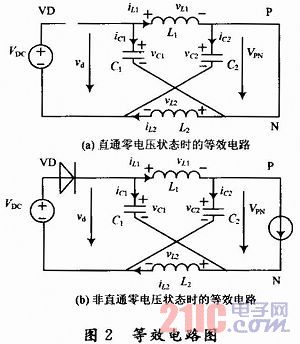
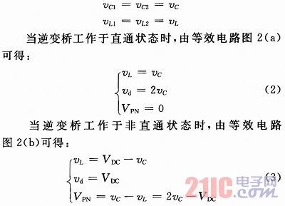
Assume that in one switching cycle T, the time when the inverter bridge operates in the through zero voltage state is T0, and the time in the non-through zero voltage state is T1, T=T0+T1, then one inductive cycle in the steady state The average voltage of the terminal must be 0, which can be derived from equations (2) and (3): 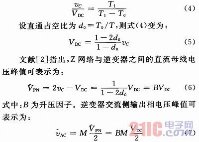
Where: M is the modulation factor of the inverter, ![]() . Obviously, by appropriately changing the boosting factor and the modulation factor, the AC side output voltage can be raised or lowered, so the Z source inverter has a flexible buck-boost characteristic. Known from the above analysis,
. Obviously, by appropriately changing the boosting factor and the modulation factor, the AC side output voltage can be raised or lowered, so the Z source inverter has a flexible buck-boost characteristic. Known from the above analysis, ![]() There is only one constant coefficient between them. As long as one of the quantities is controlled, the control of the remaining two quantities can be realized. Z-source capacitor voltage closed-loop control is usually used to stabilize the capacitor voltage within a reasonable given range, so that the output voltage remains stable.
There is only one constant coefficient between them. As long as one of the quantities is controlled, the control of the remaining two quantities can be realized. Z-source capacitor voltage closed-loop control is usually used to stabilize the capacitor voltage within a reasonable given range, so that the output voltage remains stable.
The advantages of the traditional Z-source inverter mainly include: using the through-zero voltage to raise the DC voltage to achieve the boost function of the inverter output voltage, achieving wide-range voltage regulation; due to the introduction of the Z-source network, the inverter is improved. The safety of the bridge; eliminates the influence of the dead zone on the output AC voltage; reduces the switching loss and improves the power conversion efficiency. Therefore, the Z-source inverter provides a low-cost, high-reliability single-stage buck-boost inverter implementation. The above advantages of the Z-source inverter make it a potential application prospect in new energy applications where the input voltage of the fuel cell power generation varies widely.
However, further analysis found that it also has the following limitations: at light load operation, the maximum output voltage of the Z network will become higher and higher, and from the high frequency point of view, the Z network output voltage has obvious distortion; At the time of loading, the DC link voltage of the Z source inverter is divergent and the system is unstable. The converter has a startup shock problem and does not have the ability to suppress the starting shock, thereby damaging the converter.
1.2 Improvement of Z-source inverter In order to solve the above-mentioned shortcomings of traditional Z-source inverter, this paper introduces a new type of Z-source inverter suitable for fuel cell vehicle motor control.
Figure 3 shows the main circuit diagram of a high-performance Z-source inverter. The switch SW allows the current of the Z network to flow in the opposite direction; the diode VD ensures a one-way flow of the supply current; and the input capacitor C provides a path for the reverse current of the circuit. All functions of the circuit are realized by controlling the through-duty ratio and the switching tube SW.
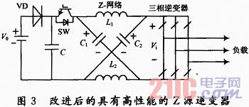
It is known from the literature that the high-performance Z-source inverter has the same relationship between the voltages of the various parts when the Z-source inverter has a small inductance and a large load variation range. . Therefore, the voltage relationship of the conventional Z-source inverter is still applicable to the improved Z-source structure.
The three special abnormal operating states of the conventional Z-source inverter in light load or small inductance are replaced by the working mode 4, the working mode 5 and the working mode 6 in FIG. 4 to ensure that the circuit works normally.
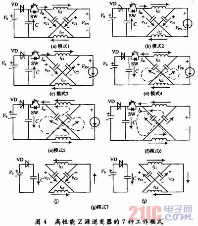
The inverter bridge switch tube in the high-performance Z-source inverter circuit can partially realize the function of zero voltage turn-on. As shown in Figure 4, when the circuit is in operating mode 6, the current in the circuit forms a loop through the input capacitor and the Z-network capacitor. If the pass-through signal is added at this time, that is, the switch SW is turned off, the current in the inductor cannot be abrupt, and the current passes through the inverse. The body diode of the bridge switch constitutes a loop, forming a special through state as shown by 1 in Fig. 4(g). This state causes the diode to clamp the DC link voltage Vi to zero voltage, while the inductor current decreases in the negative direction. When it is reduced to zero, since the through signal is already present, the inverter bridge switch has zero voltage conduction. The zero voltage turn-on of the switch tube through state is realized.
It has the following advantages: the new topology has the inherent ability to suppress the start-up shock. By adopting a suitable soft-start strategy, the soft start of the converter can be realized; the voltage distortion of the DC link is eliminated; the circuit has strong adaptability to the load, that is, Working in the environment of fuel cell vehicle speed change; simplifying the design of the Z network inductor design and control system design; can partially realize the zero voltage conduction of the inverter bridge switch tube in the through state, reducing the switching loss and improving the switch The working environment of the tube. It is more suitable for fuel cell vehicles with high power density, wide voltage range, strong transient overload capability, high reliability, large output power and reasonable cost. It has a good application prospect in fuel cell vehicles.
2 Modulation method of Z-source inverter In many inverter control algorithms, SVPWM algorithm has clear physical concept, high DC voltage utilization, fast dynamic response, and low switching operating frequency under the same output voltage waveform quality. The switch loss is small, and is widely used in the control of three-phase inverters.
In order to apply SVPWM to the new Z-source inverter, the traditional SVPWM needs to be improved. In a switching cycle, the traditional SVPWM needs to insert the through time T0 to achieve the boost function. Taking the first sector as an example, the improved SVPWM control waveform is shown in FIG.
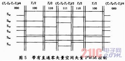
Ts is the switching period; T1 and T2 are the effective time of the effective vector (100) and (110) respectively; Tz is the zero vector action time in the traditional SVPWM, Tz=Ts-T1-T2; T0 is the through time, T0=Tz /12.
As shown in FIG. 5, the through state is uniformly distributed throughout the switching period, and the inserted through time does not additionally increase the number of switching times, and the state allocation time is as shown in FIG. 5.
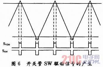
Figure 6 shows the relationship between the through signal and the switch SW drive signal. By analyzing the working state of the above circuit, it can be known that the switch SW is in the off state when the through state occurs; in order to obtain the required input current (positive current or negative current), the Z network output current (iL+iC) is not less than the load. 50% of the current, iL+iC=iPN/2, when the inverter bridge is in the non-through state, the switch SW is in the on state. That is to say, the driving signal of the switching tube SW and the through signal of the inverter bridge are in a complementary relationship.
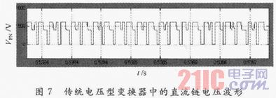
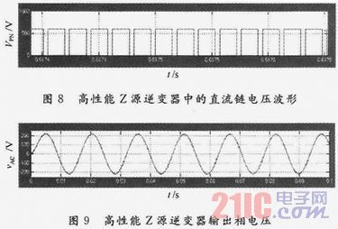
3 Simulation results and analysis This paper simulates and experimentally tests the working principle and state of high-performance Z-source inverter. The parameters of the simulation and experimental circuit are as follows: system input voltage V0=510 V; system input capacitance C=470μF; L1=L2 =100μH, C1=C2=470μF; switching frequency fs=10 kHz; straight-through duty ratio D0=0.17. Figures 7 and 8 compare the simulation results of the DC link voltage of a conventional voltage-type inverter and a Z-source inverter when the load is light (RL = 400 Ω). It can be seen from Fig. 7 that the DC link voltage of the conventional inverter has a voltage distortion phenomenon in the non-through state, and FIG. 8 shows that the high-performance Z-source inverter significantly eliminates the DC link voltage distortion phenomenon. It can be seen from Fig. 9 that the improved Z-source inverter output voltage waveform has better sinusoidality and less harmonics.
4 Conclusion AC motor drive system is the mainstream of electric drive system for electric vehicles in the future. In this paper, the new Z-source inverter topology can be used for wide-range voltage regulation in the traditional Z-source inverter; the upper and lower bridge arms of the inverter bridge can be turned on at the same time, which improves the safety of the inverter bridge; eliminates the dead zone output. At the same time of reducing the switching loss and improving the efficiency of power conversion, the Z-source inverter is proposed as an improvement measure for the inherent shortcomings of Z-source inverters applied to fuel cell vehicles. A low-cost, high-reliability single-stage buck-boost inverter implementation is well-suited for use in fuel cell vehicles where fuel cell output voltage is unstable and requires high output power.
Choke Inductor,Pfilter Choke Inductor,Filter Choke Inductor,Choke Power Inductors
Guang Er Zhong(Zhaoqing)Electronics Co., Ltd , https://www.geztransformer.com