1) Bus matching.
There are two methods for bus matching. One is to add matching resistors. The differential ports VA and VB at both ends of the bus should be connected with 120Ω matching resistors to reduce reflection and absorption noise caused by mismatch, effectively suppressing noise. interference. However, the matching resistor consumes a large current and is not suitable for systems with strict power consumption limits.
Another more power-saving matching scheme is RC matching. Using a capacitor C to block the DC component can save most of the power, but the value of capacitor C is a difficult point, and a trade-off between power consumption and matching quality is needed.
In addition to the above two, there is a matching scheme using a diode. Although this scheme does not achieve true matching, it utilizes the clamping action of the diode to rapidly weaken the reflected signal to achieve the purpose of improving the signal quality, and the energy saving effect is remarkable.
2) Pull-up resistors are configured on the RO and DI terminals.
Asynchronous communication data is transmitted in bytes, and a handshake is performed with a low start bit before each byte is transferred. In order to prevent the interference signal from falsely triggering the RO (receiver output) to generate a negative transition, so that the receiving MCU enters the receiving state, it is recommended that the RO be connected to a 10kΩ pull-up resistor.
3) Ensure that the RS-485 chip is in the receiving input state when the system is powered on.
For the transceiver control terminal TC, it is recommended to use the MCU pin to control through the inverter. It is not appropriate to use the MCU pin to directly control to prevent the bus from interfering with the MCU when it is powered on.
4) Bus isolation.
The RS-485 bus is a parallel two-wire interface. Once a chip fails, the bus may be “pullâ€. Therefore, the two-line VA, VB and bus should be isolated. Usually, a 4~10Ω PTC resistor is connected in series between VA, VB and bus, and a 5V TVS diode is connected across the ground to eliminate line surge interference. If there is no PTC resistor and TVS diode, you can replace it with a common resistor and a Zener.
5) Reasonable selection of chips.
For example, in order to prevent strong electromagnetic (thunder) impact, it is recommended to use TI's 75LBC184 and other lightning protection chips, and SP485R with SIPEX is more required for the number of nodes.
The Description of 2G/3G/GSM/4G/5G Antenna
Frequency of 5G Antenna: 885-900mhz/1800-2170mhz
2G/3G/GSM/4G/5G Antenna is mainly used for communication, which can enhance the signal of mobile phone, computer and wireless Internet. 2G/3G/GSM/4G/5G Antenna has indoor and outdoor, Outdoor Antenna is waterproof, sun protection, lightning protection , Corrosion.
The Picture of the Description of 2G/3G/GSM/4G/5G Antenna:
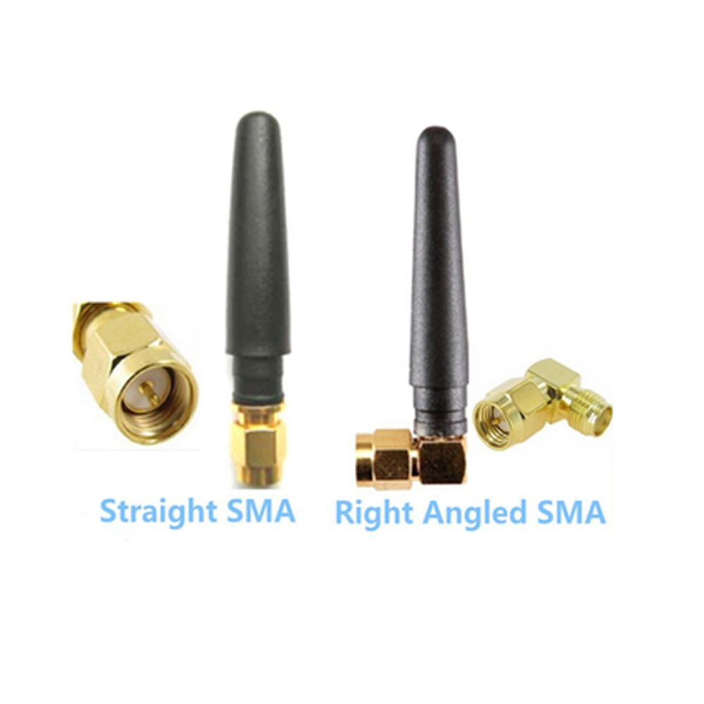
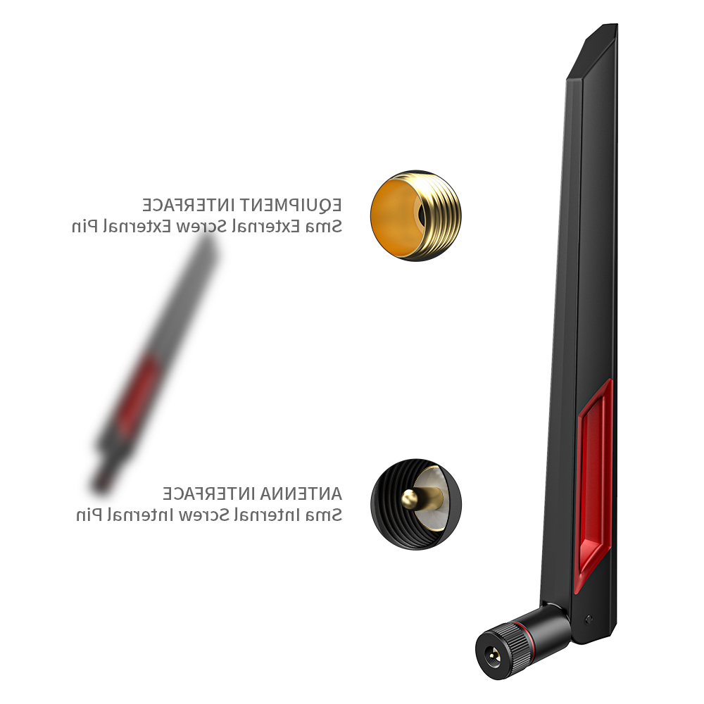
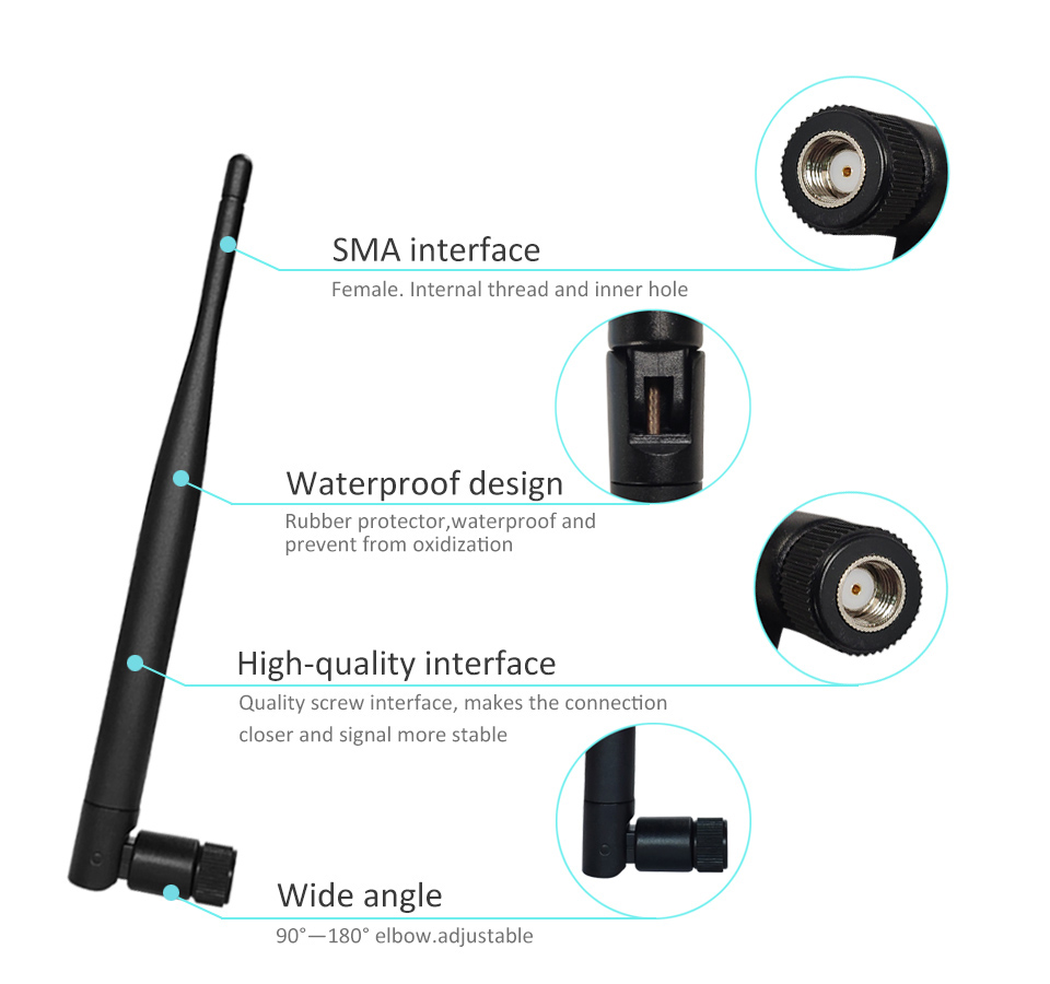
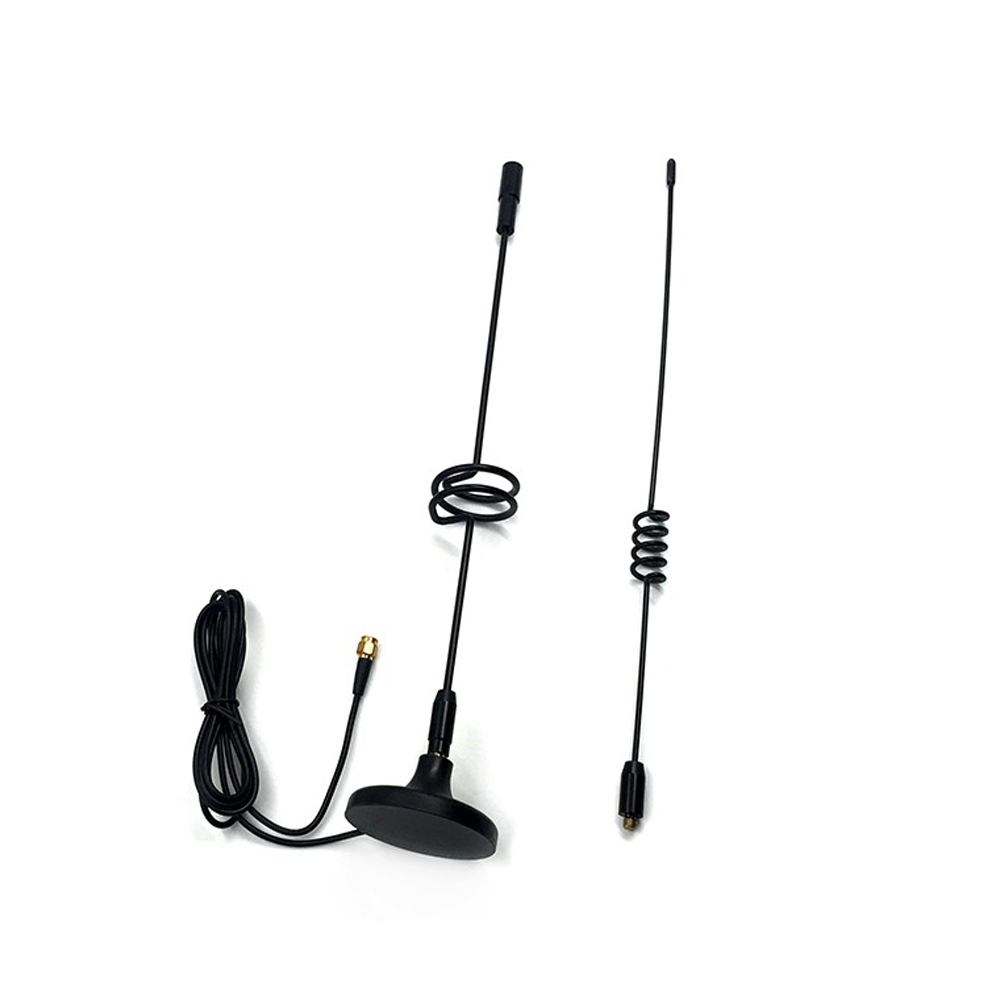
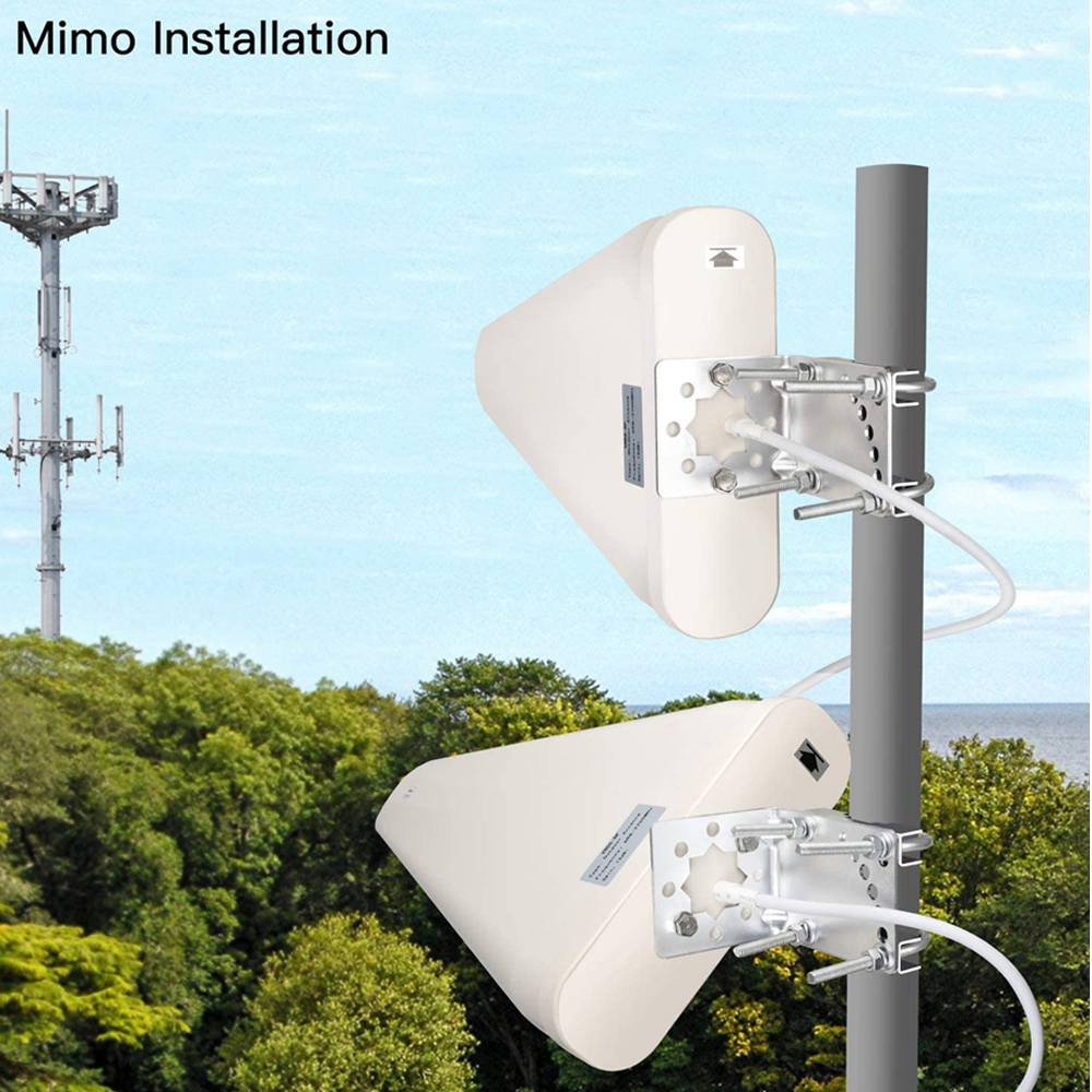
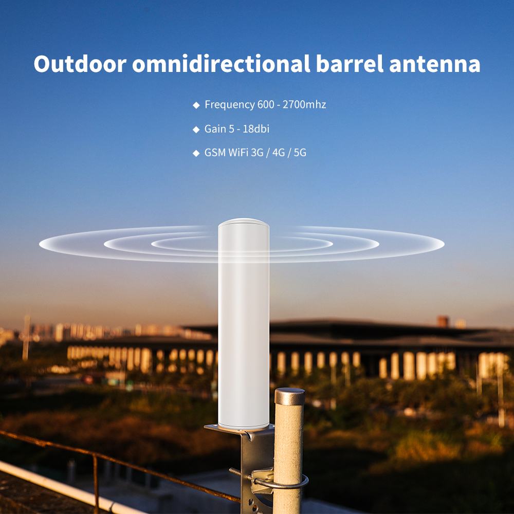
2G Antenna,3G Antenna,GSM Antenna,4G Antenna,5G Antenna
Yetnorson Antenna Co., Ltd. , https://www.yetnorson.com