Programmable Logic Controller is a digital computing operation electronic system specially designed for application in industrial environments. It uses a programmable memory that stores instructions for performing operations such as logic operations, sequence control, timing, counting, and arithmetic operations, and controls various types of mechanical equipment or production through digital or analog input and output. process.
Three common methods of PLC control inverter:
1. PLC's multi-function terminal connected to the inverter, the multi-function terminal is set to multi-channel speed function in the inverter, and the corresponding frequency is set. Through the combination of closing and opening of the PLC, the inverter is operated at different speeds.
Advantages: fast response and strong anti-interference ability.
Disadvantages: No.
2. Through the PLC and the inverter, the communication control is adopted.
Advantages: Yes, speed conversion is smooth, speed control is accurate, and adaptability is good.
Disadvantages: poor anti-interference and delay in response.
3. Through the PLC plus digital analog (DA) conversion module, convert the PLC digital signal into a voltage (or current depending on the inverter setting) signal, input to the analog control terminal of the inverter, and control the inverter to work.
advantage:.
Disadvantages: low speed regulation, not intuitive; digital-to-analog conversion module is more expensive.
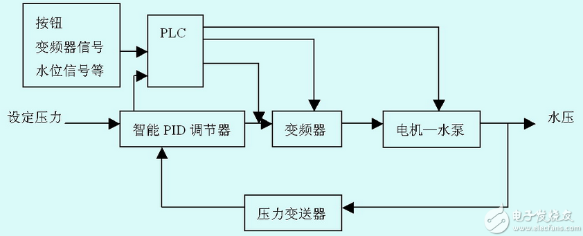
The input signal of the inverter includes a switch type command signal that operates on the running state of running/stopping, forward/reverse, jog, and the like. The inverter usually connects to the PLC using relay contacts or components with relay contact switching characteristics (such as transistors) to obtain operating status commands, as shown in Figure 1.

Figure 1 Connection method of operation signal When using relay contacts, it often causes malfunction due to poor contact; when connecting with transistors, it is necessary to consider the voltage and current capacity of the transistor itself to ensure the reliability of the system.
The correct and incorrect wiring of the input signal of the inverter are shown in Figure 2 and Figure 3, respectively. Crosstalk between the external power supply and the drive control power supply (DC 24V) sometimes occurs when the input switch signal enters the drive. The correct connection is to use the PLC power supply to connect the collector of the external transistor to the PLC through the diode, as shown in Figure 4.
Figure 2 Correct access method of the inverter input signal
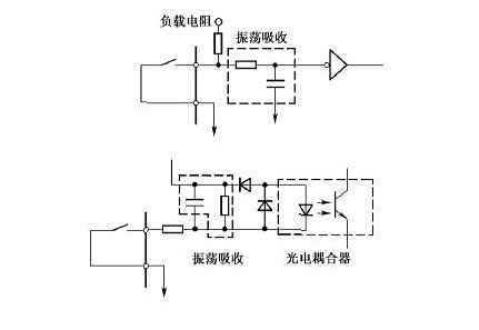
Figure 3 Incorrect access method of the inverter input signal
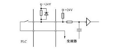
Figure 4 The collector of the external transistor passes through
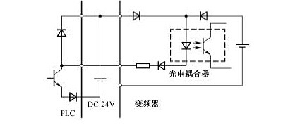
The diode is connected to the PLC. There are also some input of numerical command signals (such as frequency, voltage, etc.), which can be divided into digital input and analog input. The digital input is mostly given by the keyboard operation and serial interface on the inverter panel; the analog input is externally given through the terminal, usually input by 0~10V/5V voltage signal or 0/4~20mA current signal. . The interface circuit varies depending on the input signal, so the output module of the PLC must be selected according to the input impedance of the inverter.
When the voltage signal range of the inverter and PLC is different, if the input signal range of the inverter is 0~10V and the output voltage signal range of the PLC is 0~5V, or the output signal voltage range of the PLC side is 0~10V When the input voltage signal range of the inverter is 0~5V, due to the limitation of the allowable voltage and current of the inverter and the transistor, it is necessary to connect the current limiting resistor and the voltage dividing circuit in series to ensure that the opening and closing is not performed. Exceed the corresponding capacity of PLC and inverter interface circuit. In addition, the wiring should be separated when wiring, to ensure that the noise on the side of the main circuit is not transmitted to the control circuit.
Usually, the inverter also outputs corresponding monitoring analog signals to the outside through the terminal. The range of the electrical signal is usually 0~10V/5V (voltage signal) and 0/4~20mA (current signal). In either case, the input impedance of the PLC side must be such that the voltage and current in the circuit do not exceed the allowable values ​​of the circuit to ensure system reliability and reduce errors.
In addition, when using the PLC for sequential control, since the CPU takes time to perform data processing, there is a certain time delay, so it should be considered in more precise control. Because the inverter will generate strong electromagnetic interference during operation, in order to ensure that the PLC does not malfunction due to the noise generated by the main circuit breaker and switching device of the inverter, the following points should be noted when connecting the inverter to the PLC:
The PLC itself should be grounded according to the specified wiring standards and grounding conditions, and care should be taken to avoid using a common grounding wire with the inverter.
When the power supply condition is not good, the noise filter and the noise reduction transformer should be connected to the power supply module of the PLC and the power supply line of the input/output module. The corresponding measures should also be taken on the inverter side.
When installing the inverter and PLC in the same operating cabinet, the line related to the inverter and the line related to the PLC should be separated as much as possible.
Cables that transmit signals between the inverter and the PLC should be shielded or twisted to increase the level of noise immunity.
Product categories of Disc Stylus Pen, We are the specialized manufacturer of Stylus Pen from China. Disc Stylus Pen no need to charge, you can use it directly, it is universal, it is compatible with all brands capacitive touch screens, such as Apple, Huawei, Samsung, Xiaomi, Microsoft, Google Chrome, ect. OEM / ODM are welcome, looking forward to our cooperation.
Disc Stylus Pen,Digital Stylus Pen,Cute Ballpoint Pen,2 In 1 Stylus Pencil
Shenzhen Ruidian Technology CO., Ltd , https://www.wisonens.com