In power supply design, in order to improve energy efficiency, synchronous rectification is usually adopted, that is, MOSFET is used to replace the diode rectifier, thereby reducing the voltage drop and conduction loss across the rectifier, providing higher current capability and achieving higher system energy efficiency. However, traditional synchronous rectification has many technical challenges when used in LLC resonant converters, such as: 1) difficulty in setting the minimum on-time due to different operating frequencies; 2) premature due to stray inductance Synchronous rectification is turned off, conduction loss is increased; 3) Under the light load condition, the synchronous rectification current is reversed due to the capacitor current spike, which ultimately adversely affects the system. ON Semiconductor's new synchronous rectifier controller, the FAN6248, is optimized for LLC resonant converters to best address these challenges for energy-efficient server and desktop power supplies, large-screen LCD TVs and display power supplies, network and telecom power supplies, and high Power density adapters, high power LED lighting, and more.
Traditional Synchronous Rectification for Technical Challenges of LLC Resonant Converters1, the difficulty of setting the minimum conduction time
Minimum on-time is used to avoid noise interference. The operating frequency of the resonant circuit will vary depending on light load and heavy load. If the minimum on-time is set according to the reload condition, the synchronous rectification will be delayed due to the small on-time of the light load being too large; otherwise, the minimum on-time due to the heavy load is too small, caused by the switching noise. Abnormal shutdown. Therefore, a self-adjusting minimum on-time is required to solve this challenge.
2, the influence of stray inductance
Different packages have different stray inductances, while stray inductances cause a positive bias VLS when synchronous rectification is turned off, premature turn-off synchronous rectification, and a fixed turn-off threshold voltage results in a longer body diode Turn on to increase conduction loss. Therefore, a self-regulating turn-off threshold voltage is required.
3. Synchronous rectification current reversal under light load conditions
Since the resonant capacitor voltage amplitude is not large enough under light load conditions, the exciting current is charged to the resonant capacitor, and the switching of the MOSFET switch in the charging device produces a capacitive current spike that turns on the synchronous rectified current delay if turned on by the capacitive current spike during the switching period. Synchronous rectification causes the synchronous rectified current to reverse. Therefore, a self-adjusting delay is required to turn on synchronous rectification.
To address these challenges, ON Semiconductor has introduced the advanced synchronous rectifier controller FAN6248.
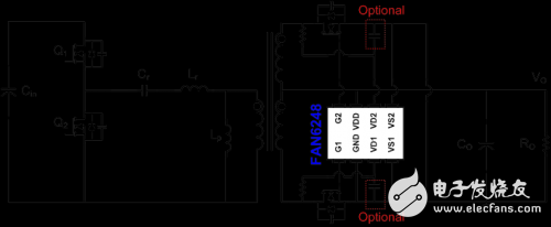
Key features of the FAN6248The FAN6248 features reverse breakdown protection to ensure reliable synchronous rectification, and its unique self-regulating dead time control compensates for parasitic inductance to maintain a constant dead time independent of output load and stray parasitic inductance. Minimize body diode conduction and maximize energy efficiency. At light load, when the capacitor current is sufficient to pre-turn the MOSFET, the FAN6248 detects the reverse current of the synchronous rectifier. By increasing the conduction delay under light load conditions, this mode of operation can be avoided, providing safe, stable and efficient operation. The FAN6248 has a self-adjusting minimum on-time circuit for better noise immunity. It has two synchronous rectification MOSFET gate drivers, and a dedicated 100 V nominal input is used to sense the drain-to-source voltage of each synchronous rectification MOSFET. Supports high frequency operation up to 700 kHz. Low operating current in energy-saving mode, typically 350 uA. Operating voltage range is 4.5 V to 30 V. The high drive output voltage of 10.5 V drives all MOSFET bands to the lowest on-resistance. Figure 1 shows a typical application circuit for the FAN6248 with an LLC controller on the primary side. On the secondary side, the configuration is very simple, including a FAN6248 controller and 2 external resistors, which may require the addition of 2 capacitors in a noisy system. Therefore, the FAN6248 is a highly integrated controller that requires minimal external components.

Figure 1: Typical application circuit for FAN6248
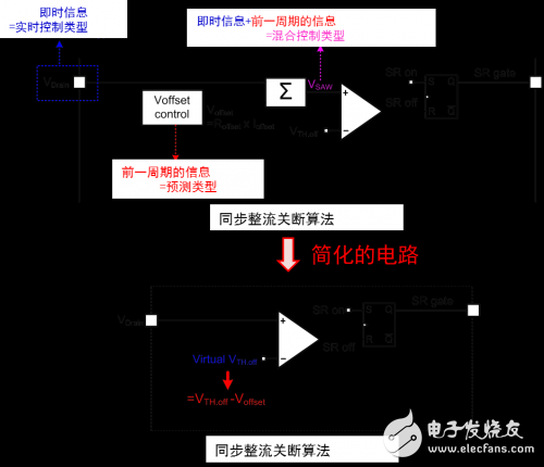
Synchronous Rectification Shutdown Algorithm for FAN6248The synchronous rectification shutdown algorithm used by the FAN6248 is based on hybrid control, which uses the instant information received by the drain node of the detection MOSFET and the information of the previous cycle to maintain a minimum dead time of 200 ns for optimum energy efficiency. This implementation can be easily analyzed with a simplified circuit where the turn-off event is determined by comparing the drain voltage to a virtual turn-off threshold, VTHOFF.

Figure 2: Synchronous rectification shutdown algorithm based on hybrid control
1, self-adjusting dead time control
When the dead time exceeds the expected 200 nanoseconds, the FAN6248 automatically reduces the compensation voltage Voffset internally, thereby increasing the virtual VTH OFF threshold, extending the synchronous rectification on-time, and reducing the dead time to nearly 200 ns. Conversely, when the dead time is less than 200 nanoseconds, the comparator virtual threshold VTH OFF is lowered, thereby shortening the synchronous rectification on-time and increasing the dead time to approximately 200 ns. Therefore, the algorithm keeps the dead time at approximately 200 nanoseconds, independent of output load and parasitic inductance.
2, self-adjusting minimum on-time control
To avoid noise interference, synchronous rectification defines the minimum on-time. The FAN6248 has an adaptive minimum on-time circuit. The minimum on-time set by the controller is 50% of the on-time of the previous cycle. The shutdown trigger is ignored during this interval.
FAN6248 eliminates the hidden danger of current reversalAt light loads, capacitive current spikes caused by parasitic effects can cause the MOSFET to be prematurely activated and falsely trigger synchronous rectification, producing a reverse current that flows from the output capacitor back to the synchronous rectifier. The FAN6248 controller increases the turn-on delay at light loads. When a current reversal is detected, the turn-on delay will increase from 80 nanoseconds at full load to 380 nanoseconds at light load to avoid false triggering of synchronous rectification and current reversal. .
Energy saving mode of FAN6248When no switch is detected for more than 240 microseconds (HA, HB version) or 420 microseconds (LA, LB version), the FAN6248 enters the power save mode. In power-saving mode, the controller stops all switching operations to reduce operating current and reduce power consumption. The operating current in this mode is 350 uA. When 11 consecutive switching cycles are detected, the synchronous rectification drive pulse is enabled again.
Two versions of FAN6248 for different application needsThe FAN6248 is available in two series, HA and HB: the HA version of VTH OFF is set at 130 mV or 228 mV for synchronous rectifier MOSFETs in larger packages such as TO220 or D2PAK; the HB version of VTH OFF is set at 100 mV or 175 mV for synchronous rectification MOSFETs in smaller packages such as PQFN or DPAK.
Energy efficiency test
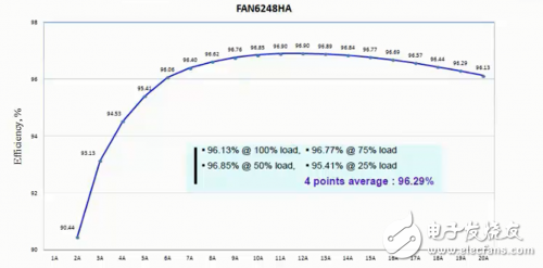
We tested the energy efficiency of FAN6248, where Vin=390 Vdc, Vout=12 Vdc, the primary controller uses NCP1399, and the full load frequency is 110 kHz. From the test waveform, the system is at full load, 75% load, 50% load. The average energy efficiency of 4 points with 25% load is as high as 96.29%.

Figure 3: FAN6248 provides energy efficiency
to sum upON Semiconductor's synchronous rectifier controller FAN6248 solves the traditional synchronous rectification technology challenge: proprietary self-regulating dead time control maintains a constant dead time (200 ns), independent of stray inductance A small on-resistance synchronous rectification MOSFET minimizes body diode conduction and maximizes system power efficiency. The reverse breakdown control ensures reliable synchronous rectification. Self-adjusting the minimum on-time provides higher noise immunity. Its reverse current detection prevents false triggering and current reversal, ensuring safe and stable operation at light loads. Low operating current in energy-saving mode enables low power consumption in standby mode. Small package (SOIC 8-pin) reduces board space and reduces cost. Powerful gate drive capability enables high power system designs up to 800 W.
Guangdong Ojun Technology Co., Ltd. , https://www.ojunconnector.com