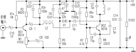
Manufacturing and circuit of varactor frequency modulation wireless transmitter
The working principle is shown in the figure, the whole transmitter is composed of low frequency amplification, varactor bias, and oscillation circuit. After the audio signal is amplified by BG1, it is sent to the varactor tube, whose capacity changes with the signal, and the frequency of the oscillation circuit is directly modulated, eliminating the parasitic amplitude modulation phenomenon of the frequency regulation using the transistor junction capacitor, and the harmonic components are few. The frequency-modulated RF signal is directly radiated from L1 into space.
The component selection inductor L1 is made of ∮1mm enameled wire wound around ∮8mm round tube for 5 turns, and the tire is hollow. L2 is made of enameled wire of ∮0.1 ~ 0.3mm on a 1 / 4W carbon film resistor with a resistance greater than 100kΩ, which is wound by 100 turns. The joints are welded to both ends of the resistor. C2, C11, C4, C3, C5 should be of high quality Ceramic capacitors. For resistance, use 1 / 8W, 0.01μF decoupling capacitor can use ordinary ceramic capacitor.
For installation and debugging, it is recommended to use the corrosion method to make the circuit board. Solder the resistance and capacitance components first, and then solder the semiconductor components. After the soldering is completed, check the + 6V power supply, and measure that the voltage of the 9014 emitter should be 0.47 ~ 0.9V to ground. If not, R1 should be adjusted. Re-measure the voltage of the emitter to the ground of 1-18V, if it is not correct, adjust R6, and then measure the voltage of the two poles of the varactor diode, or the voltage difference between the two poles is less than 0.25V. If the pressure difference between the two poles is too large, R3 or R4 can be adjusted. After adjusting the above items, turn on the FM section of the radio, receive the signal emitted by the transmitter, and pull it away to a distance of more than 5 meters. If you cannot find the signal sent by the transmitter, you can adjust L1, stretch L1, the fundamental frequency rises, and compress L1, the frequency of the fundamental wave drops, so that the transmitter frequency can avoid the local radio station, and it can be received reliably. Then connect the output signal of the player and other equipment, carefully adjust W1, so that the music is not distorted at high volume (it is not allowed to turn the volume of the player and other equipment to the maximum, but at the commonly used volume position). After the adjustment of the above items, the commissioning is basically over. Put it into a sturdy plastic or wooden box (no metal box is available) and decorate it for listening to music or as a TV sound transmitter. It is the same as the FM radio signal. Clear and stable, it can be called an "amateur professional transmitter". And no antenna is needed, and the volume is small, because there is no need to worry about the transmission distance because it is used at home.
I used it as a TV sound transmitter, connected the audio input to the audio output of the TV, powered by a 6V battery, and used a crocodile clip as a switch. The circuit board is tied to the battery with a rubber band, which can be used continuously for tens of days without worrying about running out of power.
Experimental evaluation The transmitter is simple to make, reliable in performance and low in cost. In the specific production, the circuit board used by the author is an epoxy board with low high-frequency loss. After debugging, each coil is made of high-quality high-frequency wax seal, and the effect is very good. The 5pF capacitor can be replaced by a double-sided copper-clad plate (calculated as 1pF = 1 mm2).

Dongguan Guancheng Precision Plastic Manufacturing Co., Ltd. , https://www.dpowergo.com