Schottky barrier diode (SBD) selection
Regarding the absolute maximum rating, for the same reason as the FET, the product should be selected from about 1.5 times to about 2 times the use condition. The loss of the SBD is the total value of the heat loss caused by the forward heat loss VF×IF and the reverse leakage current IR. Therefore, it is ideal to choose a product with small VF and IR. However, the relationship between VF and IR is inversely proportional to the load current. VF is large when it is heavily loaded. Considering that IR has nothing to do with the load, it is a certain value. Therefore, selecting a product with a small IR at light load has a good effect on improving efficiency. Selecting a product with a small VF at a heavy load is effective. The above content is summarized in Table 6 below.
DiagramTable 6 Points to choose SBD

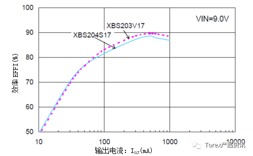
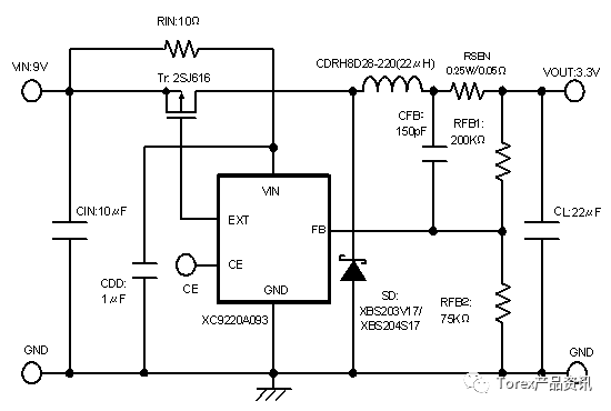
FIG. 17 shows the change in efficiency when only the SBD shown in Table 7 is changed in the XC9220A093 circuit shown in FIG. Compared with the XBS203V17, the XBS204S7 has a lower IR, so the efficiency at light load is high, and because the VF is large, the efficiency at heavy load is low.
Diagram 
Figure 17. Differences in selection and efficiency of the XC9220A093 SBD

Figure 18. Test circuit of Figure 17
XC9220A093 (down time)
Table 7 Tested various characteristics of the SBD of Figure 17

The greater the CL, the smaller the ripple, but if it is excessively large, the shape of the capacitor is also large and the cost is increased. CL is determined by the required ripple size. First, the ripple voltage of 10 mV to 40 mV is mainly targeted, and the capacitance value of Table 8 is started at the time of boosting, and the capacitance value of Table 9 is started at the time of stepping down. However, there is a danger of abnormal oscillation of DC/DC that does not support low-ESR capacitors. If low-ESR capacitors are used in continuous mode, check the load transient response in advance to confirm that the output voltage can stabilize in time (oscillation is approximately 2 Convergence within less than two times.
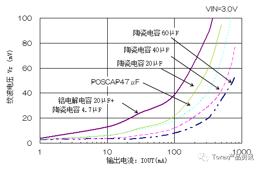
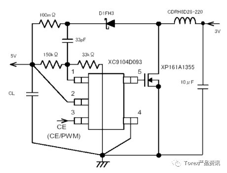
FIG. 19 shows the output ripple variation of the test after the CL was replaced in the XC9104D093 shown in FIG. The ripple is proportional to the ESR and increases in inverse proportion to the capacitance. In the case of an aluminum electrolytic capacitor, if there is no ceramic capacitor in parallel, it is difficult to obtain the output current because the ESR is too large.
DiagramTable 8 Standards for CL at Boost

Table 9 Standards for CL at Bucking


Figure 19. Output side ripple variation with CL value (XC9104D093)

Figure 20. Test circuit of Figure 19, XC9104D093
Middle & High Voltage Panel
. 3kV, 6kV, 10kV, 11kV, 35kV System
. VCB breaker: ABB, GE, Changshu
. Relay Protection
. Incoming Panel
. Feeder Panel
. Couple Panel
. PT Panel
. DC panel for breaker operation
. Contianerized High Volatge Panel system
. LCD Monitior System
Hv Panel,Hv Distribution,High Voltage Panel,Middle Voltage Panel
Guangdong Superwatt Power Equipment Co., Ltd , https://www.swtgenset.com