A photocoupler (hereinafter referred to as an optocoupler) is an optoelectronic device composed of a light emitting device and a photosensor. It enables the conversion of electrical-optical-electrical signals, and the input signal is isolated from the output signal. At present, most of the optocoupler input parts use gallium arsenide infrared light-emitting diodes, and the output part uses silicon photodiodes, silicon phototransistors and light-triggered thyristors. This is because the gallium arsenide infrared light-emitting diode with a peak wavelength of 900 to 940 nm can match the peak wavelength of the response of the silicon photovoltaic device, and a high signal transmission efficiency can be obtained.
Optocoupler structure
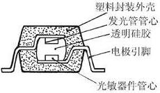
Figure 1 Internal structure of the optocoupler (profile)
The internal structure (profile) of the optocoupler is shown in Figure 1. The optocoupler input part is mostly an infrared light emitting diode, and the output part has different photosensitive devices, as shown in FIG. 2 .
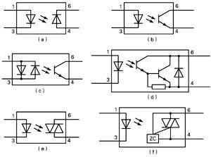
Figure 2 Schematic diagram of the optocoupler
It should be noted that the input part of Figure 2(c) has two back-to-back infrared light-emitting diodes for AC input; Figure 2(d) uses Darlington output structure, which can make the output larger. The currents of Figures 2(e) and 2(f) consist of light-triggered triacs that are primarily used to drive AC loads. The difference between Fig. 2(e) and Fig. 2(f) is that Fig. 2(f) has zero-crossing trigger control ("ZC" in the figure means "zero crossing"), and Fig. 2(e) has no zero-crossing trigger. Control circuit.
The basic circuit of the basic circuit optocoupler is shown in Figure 3. The load resistor RL of FIG. 3(a) is connected between the emitter and the ground, and the load resistor RL of FIG. 3(b) is connected between the power source Vdd and the collector.

Figure 3 The basic circuit of the optocoupler
In Figure 3(a), the VCC voltage is applied to the input terminal. After the current limiting resistor Rin, a certain current IF flows through the infrared light emitting diode. The relationship between IF and Vcc and the forward voltage drop VF and Rin of the LED is : IF = (Vcc - VF) / Rin. The VF in the formula is 1.3V. The maximum value of IF is given by the data (IF ≤ 10 mA during normal operation).
After the LED is illuminated, the phototransistor is turned on, and the collector current IC flows from Vdd through the phototransistor through RL to ground, so that the output voltage Vout=Ic×RL (or Vout=Vdd-VCE, VCE is the tube voltage drop of the phototransistor) .
The working principle of Fig. 3(b) is the same as that of Fig. 3(a) and will not be repeated. In Figure 3, the inputs and outputs can also be used in their respective locations.
It can be seen from Fig. 3(a) that the input terminal does not add Vcc voltage, the output terminal Vout=0V, the input terminal is Vcc voltage, and the load is energized. This function is equivalent to "relay". If a pulse of 5V is added to the input terminal (as shown in Figure 4), the output terminal is Vdd=12V, RL=10kΩ, then the output pulse amplitude is close to 12V. From this point of view, it is equivalent to "transformer". "; If the input voltage transitions from 0 to +5V, the output transitions from 0 to nearly 12V, which can be used as a level shifter.
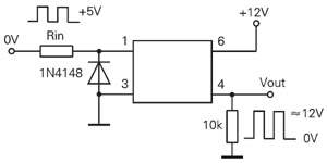
Figure 4 Level shifting of optocoupler applications
Features and application range
The main features of optocoupler: insulation between input and output (insulation voltage up to several thousand volts); signal transmission is single direction, output signal will not affect the input signal; can transmit analog signal can also transmit digital signal; anti-interference Strong ability; small size, long life; strong vibration resistance due to no contact. In recent years, due to the improvement of production technology and the development of SMT, the development of a better-performance, smaller-sized chip-type optocoupler has been improved from a DIP6 pin package to a 4-pin package, which not only reduces the size but also reduces interference. As shown in Figure 5, there are some companies whose pins are still arranged in 6 pins. The first surface has a circle and is the first pin.
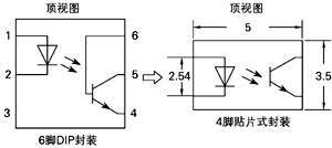
Figure 5 Schematic diagram of optocoupler pins
Because of the above characteristics, the device is mainly applied to isolation circuits, switching circuits, logic circuits, signal long-line transmission, linear amplification circuits, isolated feedback circuits, control circuits, and level conversion circuits.
Main parameters of optocoupler This paper introduces some commonly used chip optocouplers and their main parameters produced by NEC and TOSHIBA. The main parameters are shown in Figure 6.
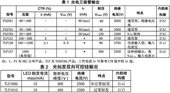
Figure 6 Optocoupler main parameters
Here we have to explain the meaning of the current transfer ratio (CTR) parameter. CTR is an abbreviation of Current Transfer Ratio. It is the ratio of the output current Ic of the optocoupler to the input current IF under certain working conditions (IF and VCE), generally expressed as a percentage, the value is from a few to several tens, and the high is from tens to hundreds. Darlington output can reach thousands. When the CTR is large, the output current Ic is large at the same IF, and the ability to drive the load is also strong (or IF is small to obtain a large Ic).
By the way, it is pointed out that when an optocoupler is used for AC signal transmission, its frequency characteristics must be considered. The optocoupler using GaAs light-emitting diodes and silicon phototransistors has a maximum operating frequency of about 500 kHz; its response time is less than 10 μs.
The back pressure VR of infrared light-emitting diodes to be noted when using is generally very low, and some VRs are only 3V. Therefore, the input terminal can not be reversed during use to prevent the infrared light-emitting diode from being broken due to excessive back pressure (can be protected by a reverse diode at pins 1 and 3, as shown in Figure 4).
Simple measurement method of optocoupler Optocoupler output optocoupler is the most widely used. If the top printed writing or dot is not clear, you can use the pointer type three-meter to measure which pin is 1 foot, and also It is easy to measure the quality of the optocoupler.

Figure 7 Schematic diagram of optocoupler measurement
Since it is composed of a diode and a triode c and e pole, it is very convenient to measure with R × 1k. As long as a diode is measured: the black pen is connected to the anode of the diode, and the red pen is connected to the cathode of the diode. The resistance is about 30kΩ, and the black end of the pen is 1 pin. As shown in Figure 7, the other three measurements should be R = ∞ (the test pen does not move). If the measured resistance of the phototransistor is not ∞, the optocoupler cannot be used.
VEIIK Micko is one of the best flavor-rich, TPD-compliant disposable vape pens in the world. Its main features:
- High-quality material: 304 stainless steel, original Japanese OCC.
- The flavor stays fresh for more than six months.
- Long-lasting: 1.5ml capacity cartridge, 310mAh capacity battery. Lasts 400+ puffs.
- Perfect flavor with the big vapor production.
- OEM support service.
The vaporizer pen is more and more popular in the international market. Because this kind of small vape is
very compact and portable, extremely convenient to use. Vaping E pen wholesale, contact us for details.
veiik micko vape,veiik micko vape pen,veiik micko disposable vaporizer,veiik micko vape bar,veiik micko vape kit
Ningbo Autrends International Trade Co.,Ltd. , https://www.vapee-cigarettes.com