Summary:
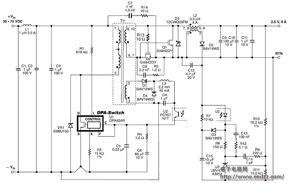
DPA-Switch greatly simplifies power supply design compared to designs that use separate devices. R1 sets the input UV/OV threshold. Strict UV/OV threshold tolerances limit the gate voltage range applied to MOSFETs Q1 and Q2, eliminating the need for a gate voltage clamp circuit. Therefore, the self-driven synchronous rectification configuration is very simple, R13 filters out the gate voltage spike of Q2, and D3 prevents the body diode of Q1 from being turned on.
The gate capacitance of capacitors C8 and Q1 resets T1 during the DPA-Switch shutdown. Zener VR1 provides a fixed voltage clamp that limits the drain voltage during output transients and overload conditions.
design feature
- Very few components
- High efficiency - with synchronous rectification efficiency of 86%
- No current sense resistor or current transformer requirements
- Output overload, open loop and over temperature protection
- Accurate input undervoltage/overvoltage meets ETSI standards
- 300 kHz switching frequency—optimized efficiency with simple self-driven synchronous rectification
20W DC-DC converter circuit diagram

See the uploading documentation for details (click to download)
Wuxi Motian Signage Co., Ltd , https://www.makesignage.com