Heart rate monitor is a commonly used medical examination equipment. Real-time accurate heart rate measurement has a wide range of applications in patient monitoring, clinical treatment and sports competition. Heart rate measurements include instantaneous heart rate measurements and average heart rate measurements. Instantaneous heart rate can not only reflect the speed of heart rate. At the same time, it can reflect whether the heart rate is uniform; although the average heart rate can only reflect the speed of the heart rate, but the record is convenient, so these two parameters are necessary in the measurement.
There are both analog and digital methods for measuring heart rate. The simulation method is to calculate the number of pulses of the R wave (or pulse wave) in a given time interval, and then multiply the pulse count by an appropriate constant to measure the heart rate. The disadvantages of this method are that the measurement error is large, the component parameters are difficult to debug, and the reliability is poor. The digital method is to measure the time between adjacent R waves, and then convert this time into the heart rate per minute to measure the heart rate. The advantages of this method are high measurement accuracy, good reliability, and simultaneous measurement of instantaneous heart rate and average heart rate. Circuits that measure heart rate digitally are divided into two types: one is to use a preset counter to implement the current divide circuit; the other is to measure the time between adjacent R waves by the automatically falling clock frequency.
Based on the digital heart rate monitor, the heart rate monitor is implemented in FPGA and VHDL language, which reduces the number of components used and improves measurement accuracy and reliability. The circuit can collect and measure the instantaneous and average heart rate of the human heartbeat in real time, and judge and display the heart rate state (ie whether the heartbeat is normal, whether it is too fast or too slow, and whether there is a heart rate disorder). If the heart rate is too fast or too slow or there is a heart rate disorder, the flashing alarm will be displayed with different color tubes.
1 Measurement method and circuit composition
1.1 Test methods
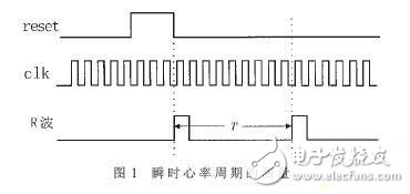
As described above, when the Intantaneous Heart Rate (IHR) is measured digitally, the time between two adjacent R waves (ie, the heart rate cycle) is measured, and then the heart rate cycle is converted into the heartbeat number per minute. As shown in Fig. 1, if the heart rate period is T seconds, the instantaneous heart rate is calculated as IHR=60/T. If the clock pulse with frequency f0 is used as the measurement time reference, the clock pulse is counted in T seconds, and the design value is N, then T=N/f0 seconds, so the formula for calculating the instantaneous heart rate is IHR=60f0/N. . When f0 = 1 kHz, IHR = 60 & TImes; 1000 / N = 60000 / N.
The Average Heart Rate is measured by averaging the instantaneous heart rates measured over a period of time. Let the measured instantaneous heart rate IHR1, IHR2, ..., IHRn, then the average heart rate is calculated as:
AHR=(IHR1+IHR2+...+IHRn)/n
1.2 circuit composition
The block diagram of the system is shown in Figure 2. Pressing the start switch will start the measurement process. The analog ECG signal (R wave or pulse wave) obtained by the sensor is amplified and applied to one input of the comparator, compared with the reference voltage of the other input, and the ECG signal is compared. Convert to a square wave signal of the same period and input it to the FPGA for heart rate measurement.
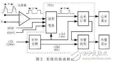
In the FPGA, the waveform conversion circuit first differentiates the square wave signal with a wide pulse width, and converts it into a square wave signal with a pulse width equal to one cycle of the clock signal (clk1), and clocks the signal through the cycle counter in the heart rate period T. Counting, and then dividing according to the instantaneous heart rate calculation formula given above can get the instantaneous heart rate. The instantaneous heart rate is converted into a seven-segment display code by the decoding circuit and sent to the three LED displays outside the FPGA for display. At the end of a measurement, the heart rate calculation module averages the measured instantaneous heart rates, and the resulting average heart rate is converted into a seven-segment display code and sent to three LED displays for display.
The alarm control module determines whether the heart rate is normal, too fast or too slow according to each instantaneous heart rate value, and determines whether there is a heart rate disorder according to two adjacent instantaneous heart rate values, respectively, with the English letter E (normal), F or S The seven-segment display code (too fast or too slow) and I (arrhythmia) are sent to the three LED displays in the alarm display circuit for display, and the three heart rate states are sent to the alarm display circuit at a frequency of 8 Hz. The three LEDs of green, red and yellow respectively display flashing alarms. Pressing the stop switch will end the measurement process and send the average heart rate to the three LED displays for display.
The system's main clock frequency is 32MHz. The clock divider circuit sent to the FPGA generates 1kHz and 8Hz clock frequencies, which are sent to the waveform conversion module, heart rate calculation module and alarm for waveform transformation, instantaneous heart rate calculation and heart rate status display. Control module. The digital circuits in the system are all realized by the FPGA chip. There are only a small number of analog devices in the periphery, including comparators, LEDs and LED displays, power circuits and crystal oscillator circuits. Therefore, the system is small in size, stable in operation and high in reliability.
Connects PC or laptop with the projector, LCD monitor, and other video display system through VGA connections
Fully shielded VGA / SVGA extension or replacement cable
Supports resolutions at 800x600 (SVGA), 1024x768 (XGA), 1600x1200 (UXGA), 1080p (Full HD), 1920x1200 (WUXGA), and up for high resolution LCD and LED monitors
Gold-plated connectors; 100% bare copper conductors
Each SVGA Cable have two high density HD15 connectors with thumbscrews
Camera Cable,Camera Usb Cable,Usb Camera Adapter,Camera Link Cable
UCOAX , https://www.ucoax.com