The I2C protocol stipulates that the transmission of data on the bus must start with a start signal and an end signal as a stop condition for transmission. The start and end signals are always generated by the master device. When the bus is in the idle state, both SCL and SDA remain high. When SCL is high and SDA transitions from high to low, it indicates that a start condition is generated; when SCL is high and SDA is low to high. A jump indicates that a stop condition is generated. After the start condition is generated, the bus is in a busy state, and the master and slave devices of the current data transfer are exclusive, and other I2C devices cannot access the bus; and after the stop condition is generated, the master and slave devices of the current data transfer will release the bus, and the bus Idle again. as the picture shows:

After understanding the start and stop conditions, let's take a look at how the data transfer takes place during this process. As we mentioned earlier, data transfer is in bytes. The master device will transmit a data bit on the SDA line during the generation of each clock pulse on the SCL line. When a byte is transferred from the high order to the low order in the order of the data bits, the slave device will pull the SDA line low. , returning a response bit to the master device, then it is considered that a byte is actually transmitted. Of course, not all byte transfers must have an acknowledge bit. For example, when the slave device can no longer receive data sent by the master device, the slave device will return a negative acknowledge bit. The process of data transmission is as shown:

As we mentioned earlier, each device on the I2C bus corresponds to a unique address. The data transmission between the master and slave devices is based on the address, that is, the master device needs to transmit valid data. First specify the address of the slave device. The process of address designation is the same as the process of data transfer above, except that the address of most slave devices is 7 bits, and then the protocol specifies that a lower bit is added to the address to indicate the next data transmission. Direction, 0 means that the master device writes data to the slave device, and 1 indicates that the master device reads data from the slave device. as the picture shows:

2 bidirectional serial lines, one data line SDA, one clock line SCL.
The SDA transmission data is a big endian transmission, which is 8 bits per transmission, that is, one byte.
Support for multi-master (mulTImastering), only one master at any point in time.
Each device on the bus has its own addr, a total of 7 bits, and the broadcast address is all 0.
There may be multiple chips of the same kind in the system. For this reason, addr is divided into fixed part and programmable part. The details depend on the chip and look at the datasheet.
1.1 I2C bit transmission
Data transmission: When SCL is high, if the SDA line is stable, then the data bit is transmitted on SDA; if the SDA is hopping, it is used to indicate the beginning or end of a session (later)
Data change: When SCL is low, the SDA line can change the transmitted bit.

1.2 I2C start and end signals
Start signal: When SCL is high, SDA transitions from high level to low level and starts transmitting data.
End signal: When SCL is high, SDA transitions from low level to high level and ends transmitting data.

1.3 I2C response signal
The Master waits for the ACK of the Slave after every 8 bits of data is sent.
That is, in the ninth clock, if an ACK is sent from the IC, the SDA will be pulled low.
If there is no ACK, SDA will be set high, which will cause the Master to have a RESTART or STOP process, as shown below:

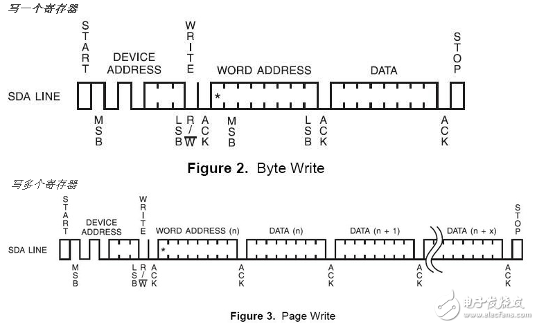
1.4 I2C writing process
The standard flow for writing registers is:
1. Master initiates START
2. Master sends I2C addr (7bit) and w operation 0 (1bit), waiting for ACK
3. Slave sends ACK
4. Master sends reg addr (8bit), waiting for ACK
5. Slave sends ACK
6. Master sends data (8bit), which is the data to be written to the register, waiting for ACK
7. Slave sends ACK
8. Steps 6 and 7 can be repeated multiple times, ie multiple registers are written sequentially
9. Master initiates STOP

SHENZHEN CHONDEKUAI TECHNOLOGY CO.LTD , https://www.siheyidz.com