1 Introduction
This article refers to the address: http://
With the development of network and multimedia technologies, the importance and demand for visual communication has increased dramatically, such as desktop video conferencing, mobile terminals, Internet-based video communications, and the like. These visual information is rich in content, but the amount of data is large and data must be compressed. However, using a variety of methods to compress image data, the amount of data is still huge, which puts high demands on computer processing speed, transmission medium, transmission method and storage medium. Therefore, data compression, as one of the key technologies of data image processing, is of great value for studying image compression coding technology.
Among embedded microprocessors, DSP has the advantages of flexibility, high speed, and easy embedded application, especially suitable for complex algorithm processing applications. The digital video image compression system uses DSP as its embedded platform to give full play to its performance advantages, improve coding efficiency, and meet the real-time processing needs of images. Therefore, a video compression system based on the TMS320VC5509A DSP is introduced here.
2 compression coding standard JPEG for still images
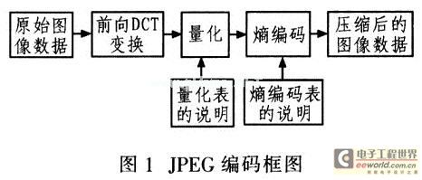
JPEG (Joint Photographic Experts Group) is a standard for still image coding proposed by the International Organization for Standardization (ISO). The processing method uses discrete cosine transform, quantization, Z-line scanning, run-length coding, and invariant word length coding. The JPEG algorithm defines the following four modes of operation:
(1) The image is scanned and encoded in order from left to right and top to bottom based on the DCT sequential mode, which is called a basic system.
(2) Encoding an image in order from coarse to fine based on the DCT increment mode, which is suitable for occasions where the transmission time is long and the user likes the image from rough to clear.
(3) The distortionless coding mode ensures that the reconstructed image is identical to the original image.
(4) Hierarchical coding encodes images using various resolutions.
The system uses the basic system model. Figure 1 is a block diagram of the encoding of JPEG.
3 hardware system design
The video compression system is directly connected to the output end of the PAL camera to acquire, preprocess and compress the live image, and then transmit the processed image data to the host computer by USB or RS232. 2 is a hardware structure diagram of a video compression system.

The hardware design of the system is based on TI's TMS320VC5509A digital signal processor, including video acquisition circuit, FPGA pre-processing circuit, memory expansion, system power supply and watchdog circuit. In the system, TMS320VC5509A is the central processing unit; SDRAM is the DSP external expansion data storage; Flash is the program memory for system power-on bootstrapping; analog camera and video A/D converter is responsible for video image acquisition; FPGA is used for address decoding, Interlaced operation controls two pieces of SRAM for buffering the digital image converted by the video A/D converter. Considering the system design cost, Altera's programmable logic device EPIC6Q240C8 FPGA is used here. This device is the most available I/O pin in a non-BGA package in the Cyclone family of devices.
3.1 video acquisition circuit
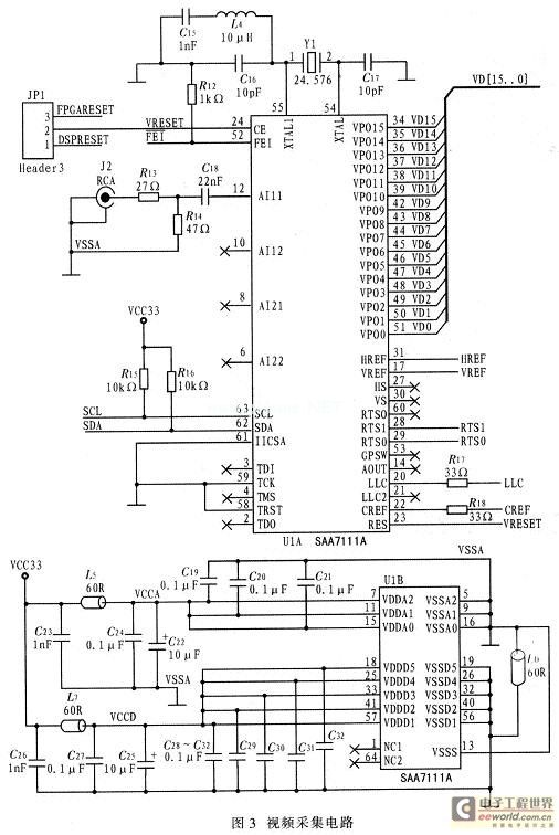
The video decoder selected for this system is Philip's high performance video A/D converter SAA7111. The device is a high-performance video input processing device widely used in desktop video, multimedia, digital TV, image processing, video telephony. The device features a 3.3 V CMOS circuit, highly integrated analog front end and digital video encoder; includes 2 analog video processing channels, 1 clock generation circuit, 1 auto-clamp and automatic gain control circuit, 1 multi-standard Digital decoder, 1 brightness/contrast/saturation control circuit, and color space matrix. The SAA7111 output is a 16-bit VPO bus that supports data output formats of different bit widths. The output formats supported by the SAA7111 include: 12-bit YUV411, 16-bit YUV4: 2:2, 8-bit CCIR-656, 16-bit 565RGB, and 24-bit 888RGB. Figure 3 shows the video acquisition circuit.
3.2 Memory Selection
The choice of memory should be considered from the following aspects: First, the image compression algorithm has a large amount of intermediate data, requiring the on-chip memory of the processor to be as large as possible, and avoiding reading and writing operations to the external memory as much as possible. The VC5509A's on-chip memory consists of 32 Kx 16-bit DARAM, 96 Kx 16-bit SARAM, and a total of 128 Kbits of memory. The DARAM is a dual address, which can be operated twice (2 times, 2 times, 1 time and 1 time) in each cycle, which greatly increases the utilization of the on-chip memory. Secondly, the VC5509A is rich in resources. Including I2C bus (multi-master-slave interface), 3 McBSPs (1 multiplexed with MMC/SD serial interface of multimedia card/digital encryption card). Using the FC bus to read and write the on-chip control register of SAA7111, it is very convenient to control the working state of SAA711 1 in real time; use McBSP with DMA, software programming to realize UART function, no special hardware UART is needed, thus saving board space: VC5509A adopts The 144-pin LQFP package is easy to install and debug. The VC5509A consumes a small amount of power and operates at 200 MHz, consumes only 100 mW, making it ideal for embedded applications.
3.3 DSP power supply circuit
The DSP base system is powered by an independent power system, while the other components of the hardware platform share another power supply system. In order to reduce system power consumption, DSP generally uses low voltage power supply. And I / O and CPU core separate power supply. The VC5509A requires different operating voltages for different operating frequencies, 1.6 V for 200 MHz, 1.35 V for 144 MHz, and 1.2 V for 108 MHz. The DSP's I/O voltage is 3.3 V.
DSP power supply circuit shown in Figure 4. The TI's two LDO power devices, the TPS76801 and TPS75833, are used to provide the core voltage and I/O voltage for the DSP.
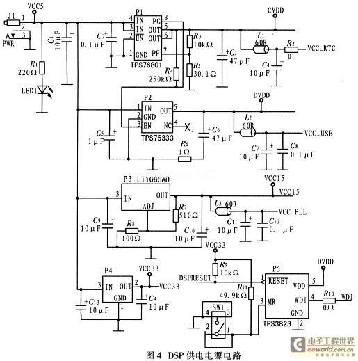
The TPS76801 can supply up to 1 A of current to the CPU core with voltages adjustable from 1.2 to 3 V.
Adjust the input resistance of the TPS76801 to get a core voltage of 1.6 V, 1.35 V, and 1.2 V. The DSP works at 200 MHz, 144 MHz, and 108 MHz. The TPS75833 can provide up to 3 A of I/O current. For the low-power TMS320VC5509A, this is enough to ensure that it is operating at maximum load.
4 system software design
The main function of the system software design is to sample the live video signal in real time, then encode and compress the network image data and transmit the image data to the host through the USB bus or RS232 serial port. The main program flow of the system is shown in Figure 5. The system software design can be divided into four main modules: system initialization, image acquisition, compression coding and data transmission.
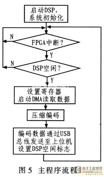
After the system is powered on, the DSP is initialized first. The initialization mainly includes: initializing the SAA7111 through the I2C bus, setting its working mode; space allocation, EMIF configuration to ensure normal access of the external memory; configuring the USB module; setting the DMA channel and setting the external Interrupted. The DSP then waits for an interrupt from the FPGA. When the DSP receives the interrupt of the FPGA, the DSP sets the flag register, starts the DMA to read the data, and encodes. When the encoding is finished, the DSP delivers the data to the USB module and transmits it to the host computer through the USB bus. At the same time, the DSP sends an idle signal to the FPGA to inform the FPGA to continue transmitting the next frame.
5 JPEG optimization
The JPEG algorithm needs to solve the coding speed problem on the DSP. The limited memory resources on the chip make most of the program code and data have to be placed off-chip. A large amount of image data is in slow SDRAM memory, and its access and arithmetic operations are one of the key factors affecting system performance. Therefore, the program should be optimized from two aspects of memory allocation and code optimization to improve coding efficiency.
5.1 Data Memory Optimization
The VC5509A's on-chip memory includes 32 Kx16-bit DARAM, 96 Kx 16-bit SARAM, and a total of 128 Kbits of memory. Among them, DARAM is dual access memory, that is, two data accesses can be completed in one cycle. SARAM is a single access memory, that is, only one data access can be completed in one cycle. The off-chip memory is extended SDRAM, and access to it requires additional Waiting time, the execution efficiency is relatively low. Therefore, the memory allocation should be reasonably arranged in the algorithm design, and the frequently accessed program code and data should be placed in the on-chip memory as much as possible, especially in DARAM, which can improve the coding efficiency.
5.2 C code optimization
In the encoding of JPEG, according to the structural characteristics of VC5509A and the combination of large amount of image data, the coding efficiency is improved. Consider programming and optimization as follows:
(1) Use compiler optimization to turn on compiler optimization options, including basic optimization, file-level optimization, and program-level optimization.
(2) Using the intrinsics function, C55x provides a special function-an eigenfunction that can quickly optimize C code. There is an underscore "one" before the intrinsic number, and the calling method is the same as the ordinary function.
(3) Using the image library, TI provides the image library IMGLIB based on C55x. The library is a commonly used function for image processing, and can be called in C language. The assembly optimization is good and the execution efficiency is high. Therefore, the library function is used as much as possible. The key to JPEG encoding is that the DCT transform can call IMG_sw_fdct_8x8 (short*fdct_data, short, *inter_buffer) in the library function. This function takes 1 078 clock cycles to complete a DCT transform. Greatly improve the coding efficiency of JPEG.
(4) Efficient use of MAC hardware, C55x has dedicated hardware to efficiently perform MAC operations. A single multiplication plus or a double multiplication (dual-MAC) operation can be performed in one cycle.
(5) Use special data types (register type, volatile type, const type). For variables that require repeated accesses, such as variable values ​​in a for loop, you can generally set them to register variables. Declaring a variable to register can improve efficiency, but it must be used with care. In some compilers, the optimizer automatically assigns some variables to the register type.
(6) Reduce the judgment loop, and try to reduce the judgment transfer when using the judgment method to select the control statement. DSP uses a pipeline structure. Because the TMS320C55X uses a 7-stage pipeline structure, frequent transfer instructions make the pipeline difficult to function.
Also. Most DSP instructions are single-cycle instructions, but transfer-type instructions typically take more machine cycles. Therefore, the branching branch in the program should be minimized to improve the efficiency of the program.
6 Experimental results
6.1 Compression effect experiment results
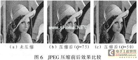
The compression ratio of the image is changed by changing the quantization factor Q. The larger the compression ratio, the greater the visual loss during compression and the less clear the compressed image. Fig. 6 is a comparison diagram of effects before and after compression using different quantization factors Q. 6a is an uncompressed original BMP image with a size of 57.4 KB, FIG. 6b is an image with a compressed size of 5.18 KB, and FIG. 6c is an image with a compressed size of 5.18 KB. It can be seen from the figure that the compressed image is not much different in visual effect from the original image. When Q=50, the required storage space of the compressed image is only 1/14 of the original image.
6.2 Compression time-consuming experiment results
For an 8x8 block, the time spent in each step is as follows: block: 1.335μs; DCT transform: 5. 39 μs; quantification: 1.355 μs; Huffman coding: 3.375 μs. It shows that the total time of an 8x8 data block is 11.455μs, and the total compression time of a frame of 720x576 gray image is 90x72x11.455=74 228.4μs, plus other auxiliary operations, the actual time is about 75 ms. According to the above results, 13 frames of 720x576 grayscale images are transmitted to the upper computer within 1 s, which basically meets the system requirements.
7 Conclusion
This paper introduces the design and implementation scheme of JPEG video compression system based on TMS320VC5509A DSP. The hardware design of this system adopts DSP+FPGA scheme, which fully exerts their respective advantages. The software design optimizes the program structure and algorithm for C55x structure. Good real-time effects. Due to its small size and low power consumption, the system is suitable for some situations where image acquisition, remote video surveillance, etc. need to continuously transmit images.
10 M Light Tower
A 10 M light tower typically refers to a mobile light tower that is 10 meters in height. These towers are commonly used in construction, mining, and outdoor events to provide lighting in areas where there is limited or no access to electricity.
The tower is equipped with multiple high-intensity lights that are mounted at the top and can be adjusted to provide wide coverage. The lights are usually powered by a generator or battery pack that is housed within the tower.
The tower itself is usually mounted on a trailer or skid for easy transportation and mobility. It can be easily moved to different locations as needed and set up quickly.
The 10 M light tower is designed to provide bright and efficient lighting for large areas, making it ideal for nighttime construction work, outdoor events, or emergency situations. It is often used in conjunction with other equipment, such as cranes or generators, to provide a complete lighting solution.
Overall, a 10 M light tower is a versatile and practical lighting solution for various industries and applications.
10 M Light Tower,High Mast Mobile Light Tower,Construction Lighting Tower,Kubota Engine Lighting Towers
Grandwatt Electric Corp. , https://www.grandwattelectric.com