OFDM can effectively suppress the deep fading caused by multipath channels, resist impulse noise and have high spectral efficiency. However, the transmission symbol of OFDM is the result of multi-carrier QAM signal after IFFT processing. Since this processing is a linear addition relationship, when there are some points with the same phase in the input of IFFT, there must be a higher peak level. Compared, the transmitter linearity is very high [1]. RF power amplifiers are the most nonlinear devices in transmitter systems. Especially for improving power efficiency, RF power amplifiers basically work in a nonlinear state. Therefore, linear power amplifier design technology has become a key technology for linearized transmitter systems. In order to ensure the efficiency of the whole system and avoid the distortion caused by nonlinearity [2], nonlinear correction technology has become increasingly important with the development of the communication industry.
2. Introduction to nonlinear correction methodThe high PAPR value of the OFDM signal causes nonlinear distortion of the system, mainly in the process of power amplification, which itself is determined by the nonlinear characteristics of the high power amplifier (HPA).
In order to obtain high efficiency and linear HPA, the nonlinear distortion must be eliminated, and the nonlinear characteristics of HPA are linearly corrected by appropriate peripheral circuits, so that the HPA and the linearization circuit exhibit a linear amplification effect on the input signal as a whole. 11]. At present, the commonly used HPA linearization methods include power back-off method, negative feedback method, feedforward method and pre-distortion method [7]. Either way, the goal is to achieve better linear input and output characteristics while maintaining higher emission efficiency.
2.1 Traditional Nonlinear Correction TechnologyBefore the advent of linearization technology, in order to avoid signal distortion caused by the nonlinearity of the power amplifier, the system designer usually chooses the power back-off method, which reduces the signal input power of the power amplifier, so that the power amplifier works in the linear working area, away from Nonlinear saturation region, which improves the intermodulation distortion of the power amplifier [12]. The power back-off method is simple and easy to implement, and does not require any additional equipment, but at the same time, the efficiency of the power amplifier is greatly reduced, thereby affecting the efficiency of the entire system.
In order to ensure the efficiency of the entire system and avoid the distortion caused by nonlinearity of the signal, linearization technology has become an important technology in the field of communication. In general, traditional linearization techniques are divided into open-loop and closed-loop. Closed-loop (such as Cartesian and polar loops) is actually a feedback technique that can achieve higher linearity but poor stability. It can only process narrowband data and is not suitable for multi-carrier systems. The open loop calibration accuracy is not as good as the closed loop, but the processing bandwidth is large and the stability is high. Feedforward technology, as another type of linearization technology, has closed-loop precision and open-loop stability and processing bandwidth, but it is complicated to implement, costly, and difficult to debug.
2.2 Digital Baseband Predistortion TechnologyA very important step in the development of linearization technology is the emergence of predistortion technology, which was originally applied to the RF part of analog communication systems. Later, with the development of digital signal processing (DSP) technology, predistortion linearization technology can also Implemented in the digital domain to form a digital predistortion technique. Digital pre-distortion technology is mainly applied to baseband or intermediate frequency, and it rarely uses RF with extremely high processing rate.
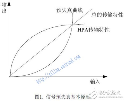
The digital baseband pre-distortion is based on the nonlinear distortion curve of HPA, finds its inverse characteristic function, and pre-distorts the input signal in the opposite direction. Thus, the total transmission characteristic after passing through HPA is linear. The basic principle is shown in Figure 1. .

The advantage of baseband pre-distortion is that the circuit is relatively simple, and after careful adjustment, it can achieve a good correction effect; strong stability, large processing bandwidth, suitable for single-carrier and multi-carrier systems, that is, independent of the modulation mode of the system; The type of HPA has nothing to do with [13];
The baseband pre-distortion technology can be implemented by means of a look-up table, that is, constructing a pre-distortion query table, and real-time processing the input signal according to the look-up table. This method can be applied to a power amplifier of any gain waveform diagram, and the linearization effect is good, but Need to take up a lot of storage space.
3. Implementation of nonlinear correction method based on FPGAThere are two schemes for achieving nonlinear correction for OFDM baseband signals. One is based on FPGA and the other is based on DSP. The advantage of the FPGA-based solution is that the integration is high, and the DSP-based algorithm is more convenient to implement and debug [6]. Because mid- to high-end FPGAs support soft CPU cores (typically such as Nios), high-level languages ​​such as C can be used to program and debug nonlinear correction algorithms, so we use an FPGA-based calibration scheme.
The digital baseband vector signal is usually decomposed into the form of two orthogonal component signals of I (real part) and Q (imaginary part).
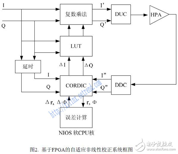
The system block diagram of our FPGA-based nonlinear correction scheme is as follows:

Wherein, I 'Q' is a signal obtained by pre-distortion of the original baseband input signal IQ, and I ''Q'' is a baseband signal obtained by radio frequency demodulation.
The calibration system mainly consists of three parts:
Lookup table module: dynamically stores the complex value calculated by the adaptive pre-correction algorithm with the input signal power value as an index. The original input baseband signal is multiplied by the value in its corresponding index term [4] to obtain the predistorted baseband signal.
Advanced and reasonable system design, stable display effect, easy installation and maintenance, high definition and high resolution. All-day work: vivid colors, high refresh rate, anti-static, dust-proof, good heat dissipation effect, and high cost performance. Display mode: move left and right , moving up and down, pulling the screen left, pulling the screen right, opening and closing in the middle, flickering, display and other methods. Using the program editing and playing software, you can edit, add, delete and modify text, graphics, images and other information through the mouse. The content of the arrangement is stored in the control card, and the information playback is automatically displayed in a loop according to the program table.
Shopping Mall Signs,Shopping Mall Led Sign Board,Shopping Center Led Billboard,Shopping Center Sign
Guangdong Rayee Optoelectronic Technology Co.,Ltd. , https://www.rayeeled.com