Design and develop a medical instrument that reconstructs the human neural network system through electromyography biofeedback, providing a new therapeutic platform for the comprehensive rehabilitation of patients with neuromuscular diseases. The therapeutic device consists of two parts: hardware circuit and PC control software. The lower computer (MCU) includes two parts: body surface electromyography acquisition and amplification circuit and neuromuscular electrical stimulation circuit. The software system of the upper computer (PC) is mainly responsible for visual signal feedback. , treatment parameter control, medical record registration, information query and other functions. The therapeutic device has reached the national medical rehabilitation treatment indicators, can help patients gradually recover, and has the characteristics of safety, non-invasive, convenient, and strong human-computer interaction.
Electromyography Biofeedback Therapy is a multidisciplinary, integrated application of knowledge and technology in physical medicine, control, physiology, anatomy, psychology, and rehabilitation medicine. It uses the myoelectric receiving device to record the weak electrical signals when the muscles contract spontaneously, and uses this as a source to provide feedback signals through visual or auditory pathways. Transforming changes in the body that are not easily perceived by people into visually audible signals, and allowing patients to learn how to self-train and adjust according to these signals. Suitable for rehabilitation of nerve and muscle injury diseases, such as stroke, spinal cord injury, high muscle tone, peripheral nerve injury, muscle atrophy, and hypertension, neurosis, urinary incontinence, etc.
1 overall designThe therapeutic device can accurately detect the EMG signal that the patient has not enough to cause the muscle to contract by applying an electrode at both ends of the muscle of the patient's treatment site, and use the biofeedback technique to make the electromyographic value of the biosignal of the patient's self-consciousness. Visual and graphical feedback is presented to the patient, allowing the patient to re-sensitize their physiological signals and existing functions. Through the correct guidance and help of the therapist on-site, the cognitive re-learning method is used to mobilize and stimulate the patient's active participation consciousness, “awake†the patient's will process, and let the patient re-establish a positive and active cognitive process.
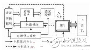
Since the EMG signal collected by the patch electrode is very weak, it is μV level. The system is designed to be properly amplified by the front end and filtered, pre-amplified and filtered, and then transmitted to the MCU. Finally, digital filtering technology is used at the MCU end. The secondary filtering makes the display of the EMG signal more stable and clear, so as to achieve the accuracy of 0.2μV. After the above signal processing, the MCU compares the measured EMG signal amplitude with the adjustable stimulation threshold, thereby determining the patient's motion consciousness. When the EMG signal amplitude exceeds the threshold, the system emits a stimulation signal to form a feedback stimulation channel. To stimulate the patient. At the same time, the MCU will transfer the collected data to the host computer for display processing; the MCU side guarantees instant communication to cooperate with the host computer to complete various operations, and the entire functional block diagram of the system is shown in FIG. 1 .

The patient can actively adjust the level of the main reference threshold of the device according to his own myoelectric signal. When the patient can smoothly increase the EMG index to reach the reference threshold and obtain current stimulation, the system will automatically raise the evoked point and prompt the patient to increase. Muscle contraction consciousness, in order to trigger further muscle stimulation, to achieve autonomous control of muscle movements. Combine the spontaneous electromyographic signal (EMG) with the external neuromuscular stimulation signal (NMES), and use the external electrical stimulation as a reward to dissolve in the main movement of the patient's muscles. The target cell's main function closed-loop feedback stimulation pathway allows the patient to re-learn the correct and effective movement mode, strengthen or establish the patient's free control of the paralyzed limb or randomly control the residual function of the destructed muscle, thereby improving the motor function of the paralyzed limb.
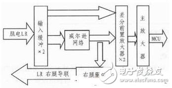
2 system detailed design 2.1 hardware module design 2.1.1 front-end signal acquisitionAs shown in FIG. 2, L and R are left and right electrodes, respectively, and LR is a right leg driving electrode. The weak signals of each electrode are sent to the Wilson network and the amplifying circuit through two input buffers. The right leg drive circuit is taken from the Wilson network center point and amplified in reverse and sent to the right leg drive electrode to neutralize the human body common mode signal.

The structure of the input buffer circuit is a voltage follower, which is highly isolated from the Wilson network. On the one hand, the extremely high input impedance overcomes the signal attenuation caused by the electrode-to-skin contact resistance; on the other hand, the extremely low output impedance ensures that the Wilson network can be effectively driven.
2) Wilson network and right leg driveThe system uses the standard Wilson network technology to transmit the interference signals induced by the human body, especially the 50Hz power frequency interference, to the center of the Wilson network as a non-central node, and the interference signals are also the same. In fact, there are also differences in the position and contact state of each electrode in the human body. The parameters of the lead line and the original value of the Wilson network also exist; discrete, so the interference signal on the non-central node of the Wilson network must have a difference in amplitude or even Phase difference. This difference will be amplified in differential mode to subsequent amplifiers. Moreover, it cannot be ignored with respect to the myoelectric (electrocardiogram) useful signal. To this end, the interference signal of the Wilson Network Center is sent to the right leg drive amplifier for reverse amplification, and transmitted to the right leg drive electrode RF, which is a kind of deep feedback to the human body interference signal, effectively weakening the human body induced common mode signal. Amplifier amplification. In an ideal case, the larger the magnification, the deeper the negative feedback, and the stronger the interference suppression capability. But in fact, the human body as a signal transmission medium, its transmission characteristics are not purely resistive, the lead leads also have distributed capacitance, too strong feedback may satisfy the self-excitation condition at a certain pi frequency, so that the circuit can not work normally. Therefore, it is better to lower Av so that the amplitude conditions are not met.
3) Signal amplificationBecause the human bioelectric signal is very weak, the noise background is strong, and the signal source impedance is very large, and the polarization difference introduced by the measuring electrode is several hundred times larger than the myoelectric and ECG signals, up to 300 mV, it is necessary to design an excellent performance. Front-end amplifier and filter circuit. Front-end amplifiers use high input impedance, high common-mode rejection ratio, low noise, low temperature drift, low nonlinearity, and suitable bandwidth and dynamic range. Therefore, the AD620 is used in this system, with a temperature drift of 60 and an input impedance of 1 MΩ, which is very suitable for front-end amplifiers. In order to prevent the dynamic range of the AD620 from being insufficient, the nonlinear region is lost and the amplification is lost. The preamplifier is taken 6 times. To further improve the common mode rejection ratio of the acquisition circuit, the system further uses the FET high impedance op amp as the input buffer. To further improve the performance of this level.
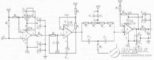
2.1.2 EMG signal preprocessing moduleBecause the myoelectric signal acts as a muscle point activity on the surface of the human body, the signal is very weak, ranging from 2μV to 4 mV, and the signal-to-noise ratio is relatively low, so it is highly susceptible to the environment. The EMG signal detected by the body surface electrode contains 7 different types of interference, namely power frequency interference, baseline drift, electrode polarization noise, ECG interference, internal noise of the amplifier circuit and motion interference, of which 50 Hz and frequency multiplication Nearby power frequency interference and baseline drift below 0.7 Hz are the two most important sources of interference. According to relevant data, the normal normal EMG signal is in the frequency range of 10 to 500 Hz, and the 90% EMG frequency energy is concentrated between 250 Hz. Therefore, it can be considered that the EMG frequency is mainly distributed between 20 and 250 Hz. In order to obtain better sampling effect, the sampling frequency band is set at 20 Hz to 1 kHz. In order to enhance the effective components in the EMG signal, suppress noise and artifacts, and improve waveform detection. Accuracy, researchers at home and abroad have proposed a variety of treatment options, generally divided into two major categories of hardware and software. In this treatment device, we have adopted both hardware and software solutions. Here, only the hardware solution is discussed. As shown in Figure 3, the first stage is a high-pass filter with a cutoff frequency of 20 Hz or less, the second stage is a low-pass filter with a cutoff frequency of 600 Hz or higher, and the third stage is 50 Hz notch. In this way, the stronger part of the myoelectric signal can be well maintained, and the 50 Hz power frequency interference is filtered out.


25 Ft Ethernet Cable,Ethernet Cable Cat 6,Best Lan Cable,75 Ft Ethernet Cable
Zhejiang Wanma Tianyi Communication Wire & Cable Co., Ltd. , https://www.zjwmty.com