Abstract of digital voltmeter based on ICL7107 With the development of science and technology, there are more and more types of digital voltmeters, and the functions are more and more abundant. Of course, the fields of application are more and more extensive, which brings many conveniences to people's work and life. . This paper mainly introduces the design based on the design of ICL7107 digital voltmeter. ICL7107 is widely used in digital measurement system. It is a large-scale integrated circuit integrating three-semi-converter segment driver driver. ICL7107 is widely used at present. A 31/2-bit A/D converter for digital measurement systems can directly drive a common anode digital display, which is a digital voltmeter. This circuit is simple and complete, and can be modified into other circuits, such as digital electronic scales. Measurement tools for specialized sensors such as digital thermometers. ICL7107 is widely used in digital measurement systems. It is a large-scale integrated circuit integrating three-and-a-half converter segment drivers and bit drivers. It is mainly used for measuring different voltages and many engineering applications, FM interface circuits. It uses the double integral principle to complete A/D conversion, and all conversion circuits are designed with CMOS LSI. The ICL7107 chip digital tube display is applied. The first leg of the chip is powered. When the voltage is correct, the DC5V is connected. The power supply connects the items to be measured to the two ports of the meter, so that the desired result can be seen on the display. In the software design, the main program to realize the adjustment of the counting frequency and the function of the single-chip microcomputer is mainly written. Finally, the software design and the hardware design are combined and then debugged. This paper describes the specific hardware structure and function in the hardware design and the program written in the software design and the corresponding debugging process.
Directory Summary 2
Chapter 1 Introduction 3
1.1 Overview of Digital Voltmeter 3
1.2 Structure of digital voltmeter 4
1.3 Digital voltmeter application area 4
1.4 Design Purpose 4
Chapter II Course Design Plan, Requirements, Task Experiment Principle 5
2.1 program selection 5
2.2 System Block Diagram 6
2.3 Design Requirements 6
2.4 Design Task 7
2.5 Experimental Principles 7
ICL7107 8
Chapter 1 Introduction 1.1 The digital voltmeter is a commonly used electrical measuring instrument. The basic principle and application technology of the electric meter are indispensable in the electrical experiment. We introduce the basic principle and application technology of the digital electric meter into the ordinary electrical experiment. The reason is:
Digital instrumentation is becoming more and more widely used;
The basic principle of the digital electric meter is simple, and it is also a comparative method for comparing the charging and discharging time of the capacitor under the voltage Vx to be measured and the reference voltage.
Understand the basic principle of digital electricity meter and the role of the external components of the common analog-to-digital conversion chip, the parameter selection principle can be used in the multimeter design to flexibly apply the digital-to-digital analog-to-digital conversion chip.
With the development of science, digital voltmeters are becoming more and more widely used. The following describes the composition and application fields of digital voltmeters.
1.2 Structure of the digital voltmeter The digital voltmeter has the following components:
ICL7107 chip \ LED digital display \ three and a half drive \ segment drive \ bit drive digital voltage has the following nine characteristics:
1. The display data is intuitive and the degree is accurate.
2. High accuracy.
3. High resolution.
4. Wide measurement range.
5. Strong expansion ability.
6. The measurement rate is high.
7. The input impedance is high.
8. High integration, micro power consumption.
9. Strong anti-interference ability.
1.3 Digital Voltmeter Applications Digital voltmeters are commonly used for the following tasks:
1. Measurements on some engineering;
2. Complete the conversion of large-scale integrated circuits;
3. Applied to large-scale digital measurements;
4. Realize the application of three-and-a-half integrated circuits and the application of other circuits;
This paper mainly studies the application based on ICL7107 chip and digital display counter.
1.4 Design Objectives 1. Consolidate what you have learned by using digital circuits and analog circuits.
2. Understand how the double integral A/D converter works.
3. Master the method of ICL7107 to form a digital DC voltmeter.
4. Understand the extended application of digital display circuits.
5. Understand the basic ideas and methods of product design.
6. Master the selection methods and component parameters of common electronic components.
7. Enhance the ability of computer to use, access data and independently complete circuit design.
The second chapter of the curriculum design, requirements, tasks, experimental principles, 2.1 program selection The main chips of this design are ICL7107 and common anode semiconductor digital tube LED.
The main features of this program are:
1. It can directly drive the common anode LED display, without the need to add the original drive, so that the whole circuit is simplified.
2. Powered by two groups of +5V and -5V power supplies.
3. LED is the original battery control, the chip itself consumes less power.
4. The display brightness is high.
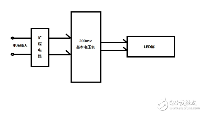
2.2 System Block Diagram The voltmeter of this paper is a digital voltmeter with 3-bit half DC voltage measurement. The design range is 20.0V and can display a negative voltage. The voltage value is stable and the reading is convenient.
2.3 Design requirements 1. Use the chip ICL7107 to achieve circuit functions;
2. Select suitable resistors, capacitors, liquid crystal displays and other devices;
3. Complete the theoretical design, fabrication, and debugging of the whole circuit, and draw the circuit schematic diagram;
4. Write a design report;
5. Turn in a production product.
2.4 Design Task 1. Design a digital voltmeter circuit;
2. Digital measurement can be achieved by design;
3. Measurement range: DC voltage 0V-20V, can display negative voltage.
4. Assemble and debug the digital voltmeter.
5. Draw a schematic diagram of the digital voltmeter circuit and write an experimental report.
2.5 Experimental Principles The following describes its pin function and selection of peripheral component parameters. ICL7107 dual integral analog-to-digital converter pin function, selection of peripheral component parameters.
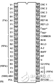
Figure 2.5-2 Pin Diagram of ICL7107 Chip The pin diagram of the ICL7107 chip is shown in Figure 2.5-2. The connection diagram of the ICL7107 is shown in Figure 4. In Fig. 4, the pin connected to the digital tube and the power supply pin are fixed, so no detailed description is given. The 32th pin of the chip is the analog common terminal, which is called COM terminal; the 34th pin Vr+ and 35 pin Vr- are the reference voltage positive and negative input terminals; the 31st pin IN+ and 30 pin IN- are the positive and negative input voltages of the measurement voltage; Cint And Rint are integral capacitance and integral resistance respectively. Caz is an auto-zeroing capacitor. They are connected to 27, 28 and 29 of the chip. The resistors R1 and C1 are combined with the internal circuit of the chip to provide a clock pulse oscillation source. From 40 feet, it can be measured with an oscilloscope. Out of the oscillating waveform, the foot corresponds to the oscilloscope interface CLK on the experiment instrument. The speed of the clock frequency determines the conversion time of the chip (because the measurement period always keeps 4000 Tcp unchanged) and the accuracy of the measurement.
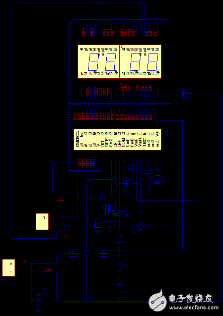
Figure 4 - Voltmeter Schematic The PCB board designed by the schematic is as follows:
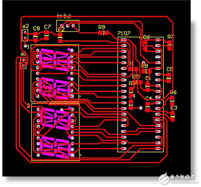
Figure 5 – PCB Figure 1.3 The LED display uses two common-digital two-digit digital tubes for display. The chip ICL7107 can directly drive the common-yang digital tube without the need for a driver circuit. The highest digit only plays the role of displaying '1' and '-', and the second digit can display the decimal point.
Commissioning work single, instrument, instrument preparation 1. Dual DC power supply (one).
2. 4-digit digital multimeter (one).
Second, the debugging content and steps 1, connect +5V power supply, connect 37 feet (TEST) +5V, digital tube segments and hundreds of decimal points are lit, indicating that the display is normal.
2. Adjust the potentiometer so that 36 feet (Vref+) is 100mV, and then connect the two test inputs to 00.0. (Note: When the reference voltage is 100mV, it is better to connect the 432 regulated power supply to debug, so as to prevent the DC voltage regulator source voltage fluctuation from affecting the debugging result)
3. Dial the 4 digits and a half digits to the 20V file as a standard table and connect them in parallel with the input terminals at both ends of the meter. Record the values ​​of the two tables with different DC voltages (see Table 1).
III. Analysis of error causes and suggestions for improvement 1. When the reference voltage is 100mV, due to the influence of 50Hz ripple, it is impossible to adjust the exact value and affect the final display voltage. For the latter two values, the parallel problem is paralleled by the input power supply. A 0.1uF and a 470uF capacitor suppress bounce and increase the cross-sectional area of ​​the ground wire.
2. In the extended circuit, the resistors of 10K and 1M are used, and the voltage division ratio is 1:101, which does not reach the accuracy of 1:100, so the error of the result is 1-3mV. Strictly use proportional resistors and use highly accurate resistors to reduce errors.
Table 1
Test voltage (V) 0.10.51510151820-5
4-digit half-value digital table (V)--1.065.0699.99414.96---
This design digital table (V)--1.055.049.9614.9---
Debugger:
***
instructor:***
2014.8.8
Digital Voltmeter Instruction Manual (1) Overview The instrument is a high-reliability digital voltmeter with stable performance and driven by a +5V power supply. The instrument adopts two common-yang LED digital tubes to form a three-and-a-half digit display with 0~19.9V, clear reading and convenient use.
The meter is designed to measure DC voltage and is an ideal tool for laboratories and maintenance workers. It is a meter with superior performance.
(B), safety matters The instrument is designed in accordance with IEC1010 (safety standards promulgated by the International Electrotechnical Commission), please read the safety precautions before use.
1. When measuring voltage, do not input a limit voltage exceeding 20V DC.
2. Before the measurement, check whether the test leads are in reliable contact, whether they are connected correctly, and whether they are well insulated.
3. The power supply terminal of the voltmeter cannot be reversed, otherwise the voltmeter will be burned, and the voltmeter supply voltage cannot be lower or higher than +5V.
4. The debug end of the potentiometer cannot be arbitrarily mobilized, otherwise it will affect the test accuracy.
(III) Description of operation surface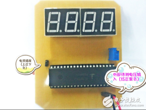
(4), characteristics 1. Display mode: LED digital tube display.
2. Maximum display: 19.9V voltage, input negative voltage automatic polarity display.
(5) How to use 1. Connect the voltage supply terminal of the voltmeter to the voltage of +5V according to its polarity.
2. Connect the test leads across the circuit under test. The voltage and polarity of the point connected to the blue line are displayed on the screen.
note:
1. The polarity of the voltmeter supply voltage, do not reverse or lower or higher than +5V or it will burn the voltmeter, or can not be tested.
2. Do not exceed 20V input voltage, otherwise the voltmeter will be burnt.
(6) Maintenance of the instrument The instrument is a precision instrument, and the user should not change the circuit at will.
Attached:
Component List Name Symbol Parameter Package Electrolytic Capacitors C1, C2, C3, C4C103, C224, C473, C103CC3216-1206
(patch)
Capacitor C5C100PCC3216-1206
(patch)
Resistor R1+R2, R3+R4, R5, R6, R7, R810K, 100K, 1M, 470K, 100K, 510ΩCC3216-1206
(patch)
Socket P1, P2 Header 2
(straight insert)
Potentiometer RP1K potentiometer (home-made in-line)
Digital tube U1, U2 common Yang DIP18 two digital tube (home-made direct plug)
Chip ILC7107 DIP40
(straight insert)
Attached:
Component list
Directory Summary 2
Chapter 1 Introduction 3
1.1 Overview of Digital Voltmeter 3
1.2 Structure of digital voltmeter 4
1.3 Digital voltmeter application area 4
1.4 Design Purpose 4
Chapter II Course Design Plan, Requirements, Task Experiment Principle 5
2.1 program selection 5
2.2 System Block Diagram 6
2.3 Design Requirements 6
2.4 Design Task 7
2.5 Experimental Principles 7
ICL7107 8
Chapter 1 Introduction 1.1 The digital voltmeter is a commonly used electrical measuring instrument. The basic principle and application technology of the electric meter are indispensable in the electrical experiment. We introduce the basic principle and application technology of the digital electric meter into the ordinary electrical experiment. The reason is:
Digital instrumentation is becoming more and more widely used;
The basic principle of the digital electric meter is simple, and it is also a comparative method for comparing the charging and discharging time of the capacitor under the voltage Vx to be measured and the reference voltage.
Understand the basic principle of digital electricity meter and the role of the external components of the common analog-to-digital conversion chip, the parameter selection principle can be used in the multimeter design to flexibly apply the digital-to-digital analog-to-digital conversion chip.
With the development of science, digital voltmeters are becoming more and more widely used. The following describes the composition and application fields of digital voltmeters.
1.2 Structure of the digital voltmeter The digital voltmeter has the following components:
ICL7107 chip \ LED digital display \ three and a half drive \ segment drive \ bit drive digital voltage has the following nine characteristics:
1. The display data is intuitive and the degree is accurate.
2. High accuracy.
3. High resolution.
4. Wide measurement range.
5. Strong expansion ability.
6. The measurement rate is high.
7. The input impedance is high.
8. High integration, micro power consumption.
9. Strong anti-interference ability.
1.3 Digital Voltmeter Applications Digital voltmeters are commonly used for the following tasks:
1. Measurements on some engineering;
2. Complete the conversion of large-scale integrated circuits;
3. Applied to large-scale digital measurements;
4. Realize the application of three-and-a-half integrated circuits and the application of other circuits;
This paper mainly studies the application based on ICL7107 chip and digital display counter.
1.4 Design Objectives 1. Consolidate what you have learned by using digital circuits and analog circuits.
2. Understand how the double integral A/D converter works.
3. Master the method of ICL7107 to form a digital DC voltmeter.
4. Understand the extended application of digital display circuits.
5. Understand the basic ideas and methods of product design.
6. Master the selection methods and component parameters of common electronic components.
7. Enhance the ability of computer to use, access data and independently complete circuit design.
The second chapter of the curriculum design, requirements, tasks, experimental principles, 2.1 program selection The main chips of this design are ICL7107 and common anode semiconductor digital tube LED.
The main features of this program are:
1. It can directly drive the common anode LED display, without the need to add the original drive, so that the whole circuit is simplified.
2. Powered by two groups of +5V and -5V power supplies.
3. LED is the original battery control, the chip itself consumes less power.
4. The display brightness is high.

2.2 System Block Diagram The voltmeter of this paper is a digital voltmeter with 3-bit half DC voltage measurement. The design range is 20.0V and can display a negative voltage. The voltage value is stable and the reading is convenient.
2.3 Design requirements 1. Use the chip ICL7107 to achieve circuit functions;
2. Select suitable resistors, capacitors, liquid crystal displays and other devices;
3. Complete the theoretical design, fabrication, and debugging of the whole circuit, and draw the circuit schematic diagram;
4. Write a design report;
5. Turn in a production product.
2.4 Design Task 1. Design a digital voltmeter circuit;
2. Digital measurement can be achieved by design;
3. Measurement range: DC voltage 0V-20V, can display negative voltage.
4. Assemble and debug the digital voltmeter.
5. Draw a schematic diagram of the digital voltmeter circuit and write an experimental report.
2.5 Experimental Principles The following describes its pin function and selection of peripheral component parameters. ICL7107 dual integral analog-to-digital converter pin function, selection of peripheral component parameters.

Figure 2.5-2 Pin Diagram of ICL7107 Chip The pin diagram of the ICL7107 chip is shown in Figure 2.5-2. The connection diagram of the ICL7107 is shown in Figure 4. In Fig. 4, the pin connected to the digital tube and the power supply pin are fixed, so no detailed description is given. The 32th pin of the chip is the analog common terminal, which is called COM terminal; the 34th pin Vr+ and 35 pin Vr- are the reference voltage positive and negative input terminals; the 31st pin IN+ and 30 pin IN- are the positive and negative input voltages of the measurement voltage; Cint And Rint are integral capacitance and integral resistance respectively. Caz is an auto-zeroing capacitor. They are connected to 27, 28 and 29 of the chip. The resistors R1 and C1 are combined with the internal circuit of the chip to provide a clock pulse oscillation source. From 40 feet, it can be measured with an oscilloscope. Out of the oscillating waveform, the foot corresponds to the oscilloscope interface CLK on the experiment instrument. The speed of the clock frequency determines the conversion time of the chip (because the measurement period always keeps 4000 Tcp unchanged) and the accuracy of the measurement.

Figure 4 - Voltmeter Schematic The PCB board designed by the schematic is as follows:

Figure 5 – PCB Figure 1.3 The LED display uses two common-digital two-digit digital tubes for display. The chip ICL7107 can directly drive the common-yang digital tube without the need for a driver circuit. The highest digit only plays the role of displaying '1' and '-', and the second digit can display the decimal point.
Commissioning work single, instrument, instrument preparation 1. Dual DC power supply (one).
2. 4-digit digital multimeter (one).
Second, the debugging content and steps 1, connect +5V power supply, connect 37 feet (TEST) +5V, digital tube segments and hundreds of decimal points are lit, indicating that the display is normal.
2. Adjust the potentiometer so that 36 feet (Vref+) is 100mV, and then connect the two test inputs to 00.0. (Note: When the reference voltage is 100mV, it is better to connect the 432 regulated power supply to debug, so as to prevent the DC voltage regulator source voltage fluctuation from affecting the debugging result)
3. Dial the 4 digits and a half digits to the 20V file as a standard table and connect them in parallel with the input terminals at both ends of the meter. Record the values ​​of the two tables with different DC voltages (see Table 1).
III. Analysis of error causes and suggestions for improvement 1. When the reference voltage is 100mV, due to the influence of 50Hz ripple, it is impossible to adjust the exact value and affect the final display voltage. For the latter two values, the parallel problem is paralleled by the input power supply. A 0.1uF and a 470uF capacitor suppress bounce and increase the cross-sectional area of ​​the ground wire.
2. In the extended circuit, the resistors of 10K and 1M are used, and the voltage division ratio is 1:101, which does not reach the accuracy of 1:100, so the error of the result is 1-3mV. Strictly use proportional resistors and use highly accurate resistors to reduce errors.
Table 1
Test voltage (V) 0.10.51510151820-5
4-digit half-value digital table (V)--1.065.0699.99414.96---
This design digital table (V)--1.055.049.9614.9---
Debugger:
***
instructor:***
2014.8.8
Digital Voltmeter Instruction Manual (1) Overview The instrument is a high-reliability digital voltmeter with stable performance and driven by a +5V power supply. The instrument adopts two common-yang LED digital tubes to form a three-and-a-half digit display with 0~19.9V, clear reading and convenient use.
The meter is designed to measure DC voltage and is an ideal tool for laboratories and maintenance workers. It is a meter with superior performance.
(B), safety matters The instrument is designed in accordance with IEC1010 (safety standards promulgated by the International Electrotechnical Commission), please read the safety precautions before use.
1. When measuring voltage, do not input a limit voltage exceeding 20V DC.
2. Before the measurement, check whether the test leads are in reliable contact, whether they are connected correctly, and whether they are well insulated.
3. The power supply terminal of the voltmeter cannot be reversed, otherwise the voltmeter will be burned, and the voltmeter supply voltage cannot be lower or higher than +5V.
4. The debug end of the potentiometer cannot be arbitrarily mobilized, otherwise it will affect the test accuracy.
(III) Description of operation surface

(4), characteristics 1. Display mode: LED digital tube display.
2. Maximum display: 19.9V voltage, input negative voltage automatic polarity display.
(5) How to use 1. Connect the voltage supply terminal of the voltmeter to the voltage of +5V according to its polarity.
2. Connect the test leads across the circuit under test. The voltage and polarity of the point connected to the blue line are displayed on the screen.
note:
1. The polarity of the voltmeter supply voltage, do not reverse or lower or higher than +5V or it will burn the voltmeter, or can not be tested.
2. Do not exceed 20V input voltage, otherwise the voltmeter will be burnt.
(6) Maintenance of the instrument The instrument is a precision instrument, and the user should not change the circuit at will.
Attached:
Component List Name Symbol Parameter Package Electrolytic Capacitors C1, C2, C3, C4C103, C224, C473, C103CC3216-1206
(patch)
Capacitor C5C100PCC3216-1206
(patch)
Resistor R1+R2, R3+R4, R5, R6, R7, R810K, 100K, 1M, 470K, 100K, 510ΩCC3216-1206
(patch)
Socket P1, P2 Header 2
(straight insert)
Potentiometer RP1K potentiometer (home-made in-line)
Digital tube U1, U2 common Yang DIP18 two digital tube (home-made direct plug)
Chip ILC7107 DIP40
(straight insert)
Attached:
Component list
| name | symbol | parameter | Package |
| Electrolytic capacitor | C1, C2, C3, C4 | C103, C224, C473, C103 | CC3216-1206 (patch) |
| capacitance | C5 | C100P | CC3216-1206 (patch) |
| resistance | R1+R2, R3+R4, R5, R6, R7, R8 | 10K, 100K, 1M, 470K, 100K, 510Ω | CC3216-1206 (patch) |
| socket | P1, P2 | Header 2 (straight insert) | |
| Potentiometer | RP | 1K | Potentiometer (home-made in-line) |
| Digital Tube | U1, U2 | Gongyang DIP18 | Two digital tubes (home made straight) |
| chip | ILC7107 | DIP40 (straight insert) |
LANA Vape E-liquids is so convenient, portable, and small volume, you can choose the flavors you like, then add into your lana vape.
We are China leading manufacturer and supplier of Disposable Vapes puff bars, lana vape e-liquids 30ml,lana vape e-liquids energy,
lana vape e liquids e-cig,lana vape e-liquids for pods, and e-cigarette kit, and we specialize in disposable vapes, e-cigarette vape pens,
e-cigarette kits, etc.
lana vape e-liquids 30ml,lana vape e-liquids energy,lana vape e liquids e-cig,lana vape e-liquids for pods,lana vape e-liquids salt nic
Ningbo Autrends International Trade Co.,Ltd. , https://www.mosvapor.com