The servo control board literally means the board used to control the steering gear. Just like driving a DC motor, the servo used by the robot also needs to be driven exclusively. We learned that the steering gear's driving method is microcontroller output through the steering engine's knowledge. The specific PWM signal, after the servo receives the signal, is compared with the internal circuit of the servo and then drives the internal small DC motor to drive the reduction gear set to make the servo's output shaft rotate to the specific angle position.
The servo control board is actually a piece of MCU development board from the hardware, a single chip microcomputer plus some peripheral circuits, but because the developer writes the multiple servo control program into the single chip microcomputer, this seemingly ordinary MCU development board It has different value, which is the charm of software development.
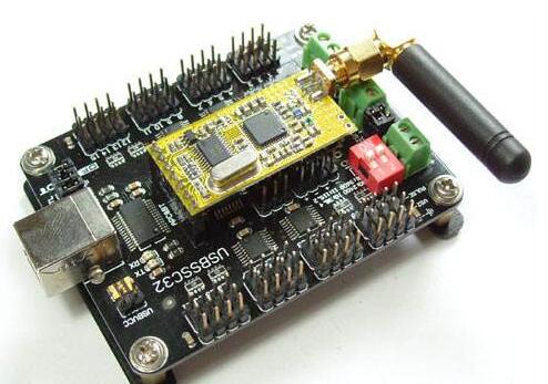
1, using 32 ARM core processor chip
2, original online upgrade mechanism, users can upgrade firmware online
3, automatically identify the baud rate
4, using USB and UART communication interface
5, 1us control accuracy (equivalent to 0.09 degrees servo)
6, can simultaneously control 32 servos (24 servo control panel can simultaneously control 24, 16 servo control panel can simultaneously control 16 servos)
7, built-in 512K memory chip, can store hundreds of action group
8, powerful computer software (built-in 3 languages, Simplified Chinese, Traditional Chinese, English)
9, have Android mobile phone control software (need to use with the Bluetooth module)
The servo control board requires two power sources: servo power and chip power (the power of the servo is relatively large, so it is not recommended to share one power supply)
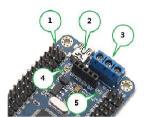
Servo power (positive): VS (right of the blue terminal in position 3)
Servo power (negative): GND (in the middle of the blue terminal in position 3 in the figure)
The parameters of the rudder analysis power source are determined according to the actual parameters of the rudder material L. For example, the supply voltage of the TR213 servo is 4.8-7.2V, then the servo power supply can use a voltage between 4.8-7.2V.
Chip power supply (positive): VSS (left end of blue terminal block at position 3 in the figure)
Chip power supply (negative): GND (in the middle of the blue terminal block at position 3 in the figure)
The VSS requirement is 6.5-12V. If the chip power supply is input from the VSS port, the voltage of the power supply must be between 6.5-12V.
In addition:
1. The USB interface at the 2nd position in the figure can supply power to the chip, so the USB interface and the VSS port are optional.
2. The position of No. 1 in the figure can also supply power to the chip, marked as 5V and GND, 5V title, GND is negative, and the voltage of the power supply must be 5V.
3, in the figure 1,2,3 position can give power to the chip, you can choose it. (But they must be powered strictly in accordance with their scope.)
4. The green LED at the 4th position in the figure is the normal indicator light of the chip power supply. The green light indicates that the chip power supply is normal and the green light is off, indicating that the chip power supply is abnormal.
5. The green LED light at position 5 in the figure is the normal indicator light of the servo power supply. The green light indicates that the servo power supply is normal and the green light is off, indicating that the servo power supply is abnormal.
If you need to control the steering gear, two green LED lights are the prerequisite.
Servo Control Board Instructionsinstall driver
Driver download address: http:// down/usc. driver.exe (all lowercase)
Double-click usc_driver.exe and click Next to install the driver.
If the following prompt appears during the driver installation, select "Always install this driver software."
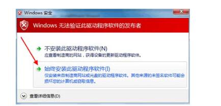
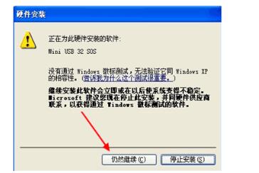
If the following prompt appears during the driver installation, select "Continue".
After the driver is successfully installed, enter the computer's device manager, and then you can see the hardware of the rudder l control board. The miniUSB servo control in the figure below is the device name, and COM472 is the terminal [number] (each computer display end [No. 1 is not the same type]. When using the computer software to control the steering gear, you need to know the port number of the device.

Connect steering gear to servo control board
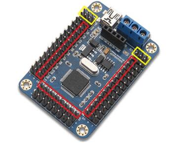
The red mark in the figure indicates the direction of the servo signal line connecting the servo
The yellow mark is not the interface of the servo
When connecting to the servo, notice the white text mark next to it, such as S1, 2. . .32, which represents the channel of the servo, corresponds to the computer software.
Download software
Software download address: http:// usc exe (all lowercase)
Control a single steering gear
Run rios. usc.exe, then select the correct end [number (cannot just select), then click the button "Open".
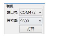
Then use the mouse to drag the slider in the servo panel (the servo is connected to the first few channels, you must drag the corresponding servo panel, the panel above is the number, as shown below S1)

(The digital box on the left side of the panel is the PWM pulse width of the current output. The box on the right has no meaning for the moment)
Simultaneously control multiple servos
Follow the above steps to control multiple servos one by one, and then set the time (as shown in the figure below, the setting is 1000ms, representing the rotation speed of the servo, the range must be between 100-9999, the larger the value, the slower) Then click on the “Add†button below the software. At the moment, a command will be generated below the software. This command can control all the servos controlled in the front (if the front controls 10 servos, the command can be simultaneously Control the 10 servos).
After the modification, it is also possible to continue to "add" multiple times, and each "add" once represents an action of the robot.

Download Action Group
Following the above steps, after producing a few or dozens of commands, you can test the effect of the command by clicking the "Run" button on the right side of the software.
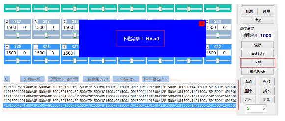
If the effect is fine, you can download the action group by clicking the "Download" button on the right side of the software.
After the download is successful, the software will prompt "Download is complete! No. = 1", the number in the prompt is the number of this action group.
After only executing this action group, all commands below this action group can be executed.
Action group
First click the "Read" button to get the number of all action groups, then enter the number of times to execute, and then click the "Execute" button to execute the selected action group.
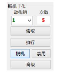
Use work offline
First click on the "Read" button to get the number of all action groups, then enter the number of times to perform, and then click the button "offline".
You can set the selected action group to be executed offline (offline execution means the control board is powered on).
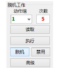
If you do not need the control board to work offline, you can click the button "disable" to turn off the offline function.
Erase Flash
Delete all action groups that have been downloaded from the dashboard.
Panel settings
Click "Panel Settings" -> Panel Edit Mode in the upper left corner. In this mode, you can drag the position of 32 panels, click the button to hide & show the corresponding panel.
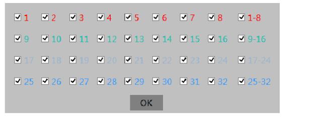
Clicking "X" will automatically save the panel's position and display hidden information.
Gaming Headphone speaker:
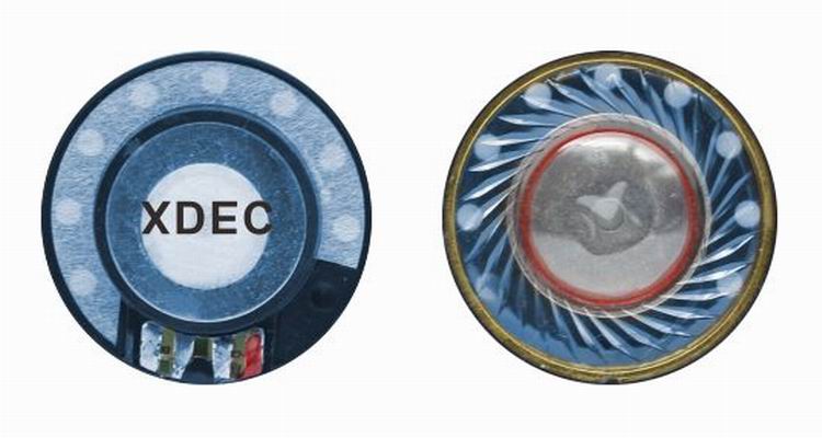
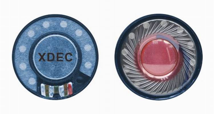
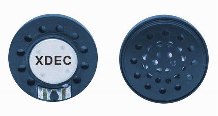
Headphone speaker is a king of speaker unit which is used for headphone, it also called headphone driver. These speakers have high sound pressure level, fast frequency response, wide frequency response range and low distortion. Headphone Speakers are mainly used for voice headphone (e.g. customer service phone, call center headphone, military intercom headset- ) and music headphone (e.g. Bluetooth headphone, sport headphone, game headphone-).
Our main headphone speakers include:
1) From the diameter, we have speakers in 23mm ~ 57mm.
2) From the impedance, we have speakers of 32ohm/150ohm/300ohm/1000ohm.
FAQ
Q1. What is the MOQ?
XDEC: 2000pcs for one model.
Q2. What is the delivery lead time?
XDEC: 15 days for normal orders, 10 days for urgent orders.
Q3. What are the payment methods?
XDEC: T/T, PayPal, Western Union, Money Gram.
Q4. Can you offer samples for testing?
XDEC: Yes, we offer free samples.
Q5. How soon can you send samples?
XDEC: We can send samples in 3-5 days.
Game Headphone Speaker,Headphone Jack Speaker,Wireless Speakers,Wireless Headphones Speaker
Shenzhen Xuanda Electronics Co., Ltd. , https://www.xdecspeaker.com